If you have trouble understanding sequence diagrams, this guide covers the definition, notation, examples, drawing steps, best practices, and common mistakes to avoid.
What is a Sequence Diagram?
A sequence diagram is a UML interaction diagram that shows how actors, objects, or system components exchange messages over time to complete a scenario. It arranges participants horizontally and messages vertically, making the order of requests, responses, conditions, and loops easier to understand.
Sequence diagrams are widely used in software development to visualize system behavior and help developers design, analyze, and understand complex interactions. They are one of the four types of interaction diagrams in UML.
When to Use Sequence Diagrams?
Model a specific use case or scenario: Use sequence diagrams to illustrate how a system behaves during a single use case, showing the step-by-step flow of messages between objects.
Design or refine system architecture: Visualize how components such as the UI, business logic, and database interact, helping architects plan or improve system structure.
Clarify complex processes: Break down complicated workflows or logic into clear, time-ordered interactions, making it easier to understand and communicate system behavior.
Validate logic before implementation: Confirm that all necessary interactions and message flows are defined correctly before coding begins, reducing design errors.
Explain system behavior to stakeholders: Use sequence diagrams to present technical interactions in a way that both developers and non-technical team members can understand.
Design or analyze integrations and APIs: Map out how services or systems exchange requests and responses to ensure smooth communication in distributed or microservice environments.
You can use Creately’s Sequence Diagram Tool to effortlessly draw sequence diagrams to design, document, and refine your system workflows.
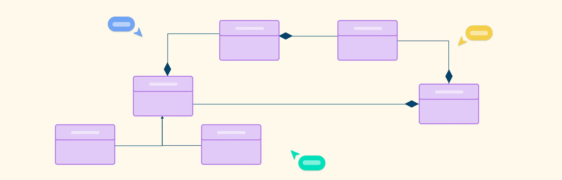
UML Sequence Diagram Symbols and Notation
A sequence diagram is structured in such a way that it represents a timeline that begins at the top and descends gradually to mark the sequence of interactions. Each object has a column and the messages exchanged between them are represented by arrows.
Objects and Lifelines
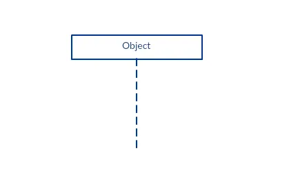
A sequence diagram is made up of several of these lifeline notations that should be arranged horizontally across the top of the diagram. No two lifeline notations should overlap each other. They represent the different objects or parts that interact with each other in the system during the sequence. Each object has a lifeline (the dash line starting at the bottom center of the object box) that indicates its existence or life span throughout the sequence of events.
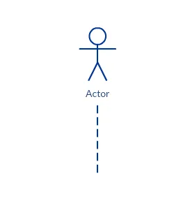
A lifeline notation with an actor element symbol is used when the particular sequence diagram is owned by a use case.
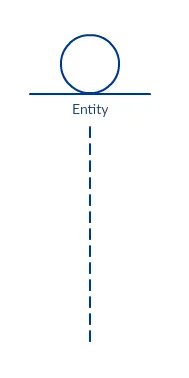
A lifeline with an entity element represents system data. For example, in a customer service application, the Customer entity would manage all data related to a customer.
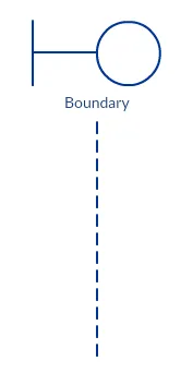
A lifeline with a boundary element indicates a system boundary/ software element in a system; for example, user interface screens, database gateways or menus that users interact with, are boundaries.
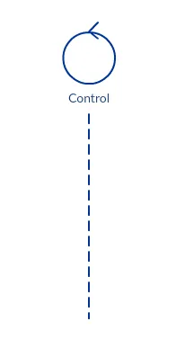
And a lifeline with a control element indicates a controlling entity or manager. It organizes and schedules the interactions between the boundaries and entities and serves as the mediator between them.
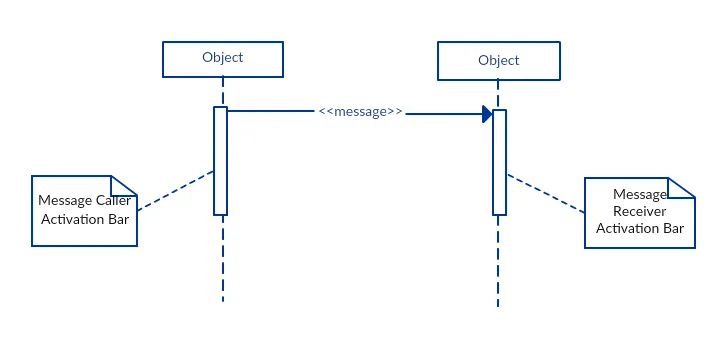
Activation Bars
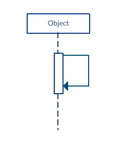
The activation bar is the box placed on the lifeline. It is used to indicate that an object is active (or instantiated) during an interaction between two objects. The length of the rectangle indicates the duration of the objects staying active.
In a sequence diagram, an interaction between two objects occurs when one object sends a message to another. The use of the activation bar on the lifelines of the Message Caller (the object that sends the message) and the Message Receiver (the object that receives the message) indicates that both are active are instantiated during the exchange of the message; the Message Caller stays active by sending the message and the Message Receiver gets activated after receiving the message
Message Arrows
An arrow from the Message Caller to the Message Receiver specifies a message in a sequence diagram. A message can flow in any direction; from left to right, right to left, or back to the Message Caller itself. While you can describe the message being sent from one object to the other on the arrow, with different arrowheads you can indicate the type of message being sent or received.
The message arrow comes with a description, which is known as a message signature, on it. The format for this message signature is below.
attribute = message_name (arguments): return_type
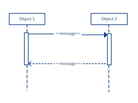
Synchronous Message
As shown in the activation bars example, a synchronous message is used when the sender waits for the receiver to process the message and return before carrying on with another message. The arrowhead used to indicate this type of message is a solid one, like the one below.
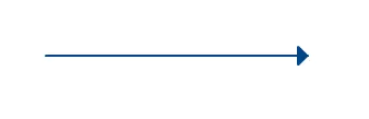
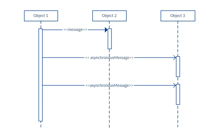
Asynchronous Message
An asynchronous message is used when the message caller does not wait for the receiver to process the message and return before sending other messages to other objects within the system. The arrowhead used to show this type of message is a line arrow as shown in the example below.
Return Message
A return message is used to indicate that the message receiver is done processing the message and is returning control over to the message caller. Return messages are optional notation pieces, for an activation bar that is triggered by a synchronous message always implies a return message.
Tip: You can avoid cluttering up your diagrams by minimizing the use of return messages since the return value can be specified in the initial message arrow itself.
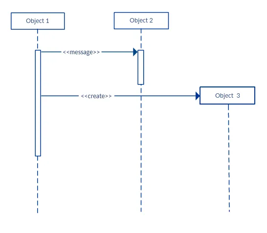
Participant Creation Message
Objects do not necessarily live for the entire duration of the sequence of events. Objects or participants can be created according to the message that is being sent.
The dropped participant box notation can be used when you need to show that the particular participant did not exist until the create call was sent. If the created participant does something immediately after its creation, you should add an activation box right below the participant box.
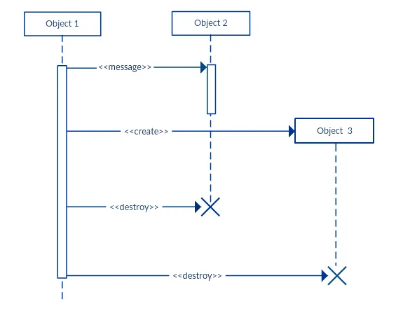
Participant Destruction Message
Likewise, participants when no longer needed can also be deleted from a sequence diagram. This is done by adding an ‘X’ at the end of the lifeline of the said participant.
Reflexive Message
When an object sends a message to itself, it is called a reflexive message. It is indicated with a message arrow that starts and ends at the same lifeline as shown in the example below.
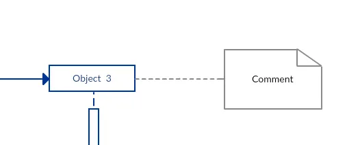
Comment
UML diagrams generally permit the annotation of comments in all UML diagram types. The comment object is a rectangle with a folded-over corner as shown below. The comment can be linked to the related object with a dashed line.
Note: View Sequence Diagram Best Practices to learn about sequence fragments.
How to Draw a Sequence Diagram
The message flow of the sequence diagram is based on the narrative of the particular use case. Before you start drawing the sequence diagram or decide what interactions should be included, you need to draw the use case diagram and ready a comprehensive description of what the particular use case does.
Step 1: Identify the Use Case
Start by defining the specific use case scenario you want to model. This sets the foundation for your sequence diagram by outlining the system’s goal and key interactions. Use Creately’s Use Case Diagram Tool to map system functions, actors, and boundaries clearly before illustrating detailed interactions in your sequence diagrams.
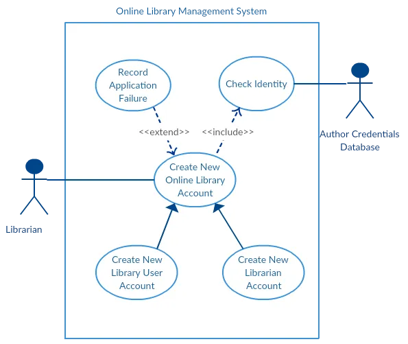
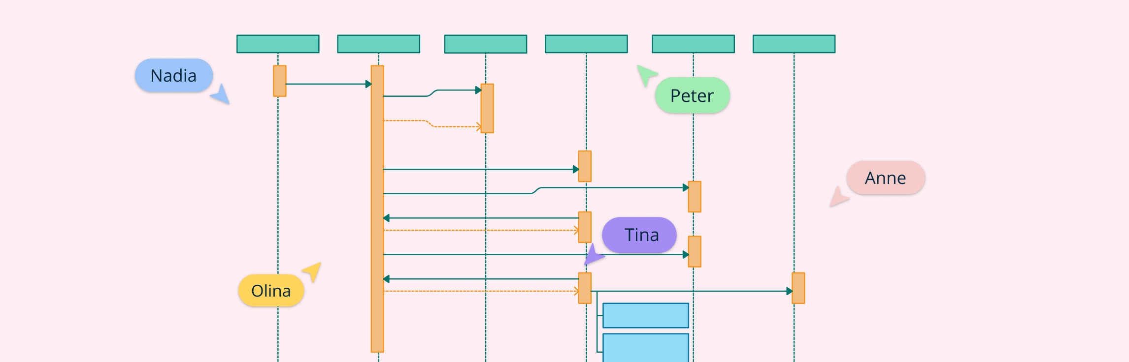
From the above use case diagram example of ‘Create New Online Library Account’, we will focus on the use case named ‘Create New User Account’ to draw our sequence diagram example.
Step 2: Identify the Objects and Actors
Before drawing the sequence diagram, it’s necessary to identify the objects or actors that would be involved in creating a new user account. These would be;
- Librarian
- Online Library Management system
- User credentials database
- Email system
Step 3: Describe the Use Case in Detail
Once you identify the objects, it is then important to write a detailed description of what the use case does. From this description, you can easily figure out the interactions (that should go in the sequence diagram) that would occur between the objects above, once the use case is executed.
Step 4: Identify Sequence of Interactions
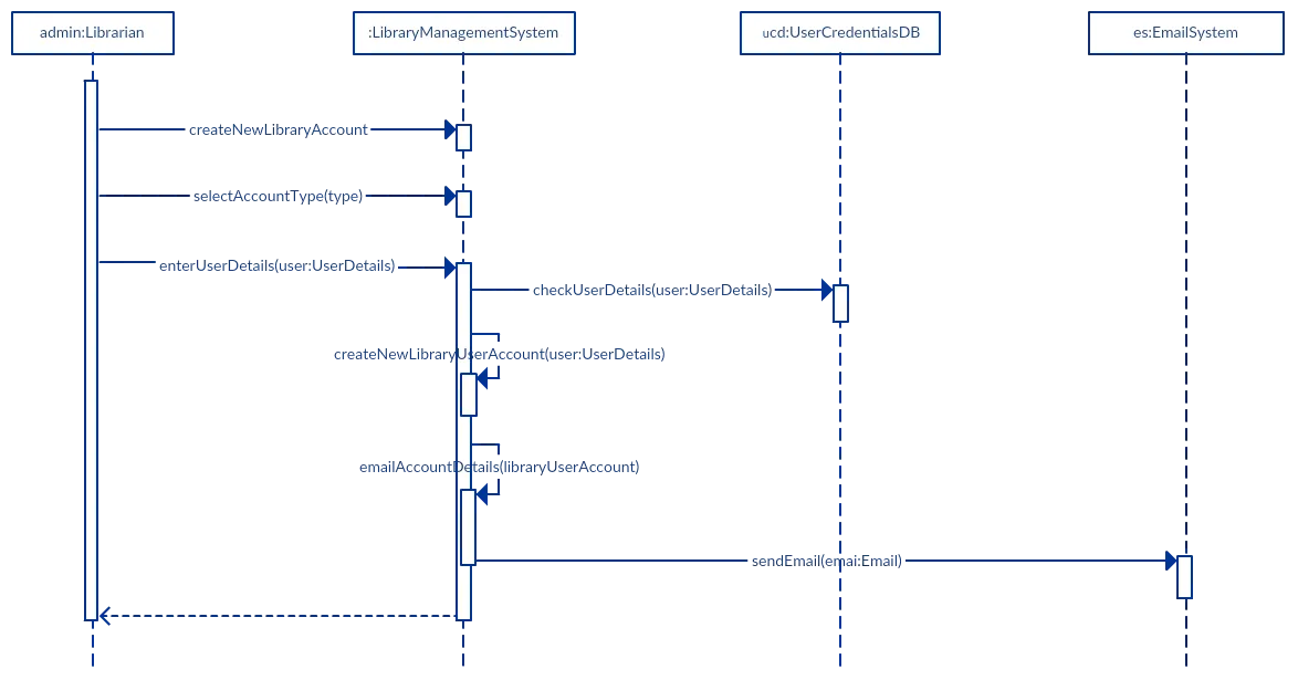
Here are the steps that occur in the use case named ‘Create New Library User Account’.
- The librarian requests the system to create a new online library account.
- The librarian then selects the library user account type.
- The librarian enters the user’s details.
- The user’s details are checked using the user Credentials Database.
- The new library user account is created.
- A summary of the new account’s details are then emailed to the user.
From each of these steps you can easily specify what messages should be exchanged between the objects in the sequence diagram.
Step 5: Open a Sequence Diagram Template
You can now begin drawing the diagram using a pre-made sequence diagram template to speed up the process and ensure accurate UML notation.
The sequence diagram below shows how the objects in the online library management system interact with each other to perform the function ‘Create New Library User Account’.
Step 6: Arrange Actors and Lifelines
Start by placing all identified actors and objects across the top of your canvas in the order they participate in the interaction. Draw lifelines as dashed vertical lines extending downward from each actor or object. Add activation bars (thin rectangles) along the lifelines to indicate when an object is active or performing an operation.
Step 7: Add Messages and Interaction Details
Once the structure is ready, begin illustrating how the objects communicate. Use arrows to represent messages or interactions:
- Solid arrows for synchronous messages (calls).
- Open arrows for asynchronous messages.
- Dotted arrows for return messages or responses.
Label each arrow clearly with the message name or method being called. Use fragments such as alt, opt, or loop if your scenario includes conditions, alternatives, or iterations.
Step 8: Review and Refine Diagram
Finally, check for clarity, correct sequencing, and alignment with the use case. Ensure all actors and system components are properly represented, and message labels remain concise and descriptive. Invite your team to collaborate directly in Creately, add comments, and refine the diagram together for accuracy and completeness.
Discover more sequence diagram templates to instantly start designing, customizing, and sharing interaction flows that visualize how system components communicate over time.
UML Sequence Diagram Best Practices
Draw smaller sequence diagrams
Instead of cluttering your sequence diagram with several objects and groups of messages that will confuse the reader, draw a few smaller sequence diagrams that aptly explain what your system does. Make sure that the diagram fits on a single page and leaves space for explanatory notes too.
Avoid unnecessary or repetitive diagrams
Also instead of drawing dozens of sequence diagrams, find out what is common about the scenarios and focus on that. And if the code is expressive and can stand on its own, there’s no need to draw a sequence diagram in the first place.
Use clear and consistent naming conventions
Name objects, lifelines, and messages clearly and consistently to avoid ambiguity. A good naming convention helps readers quickly understand which part of the system each element represents.
Maintain logical ordering and alignment
Keep lifelines evenly spaced and align messages in a consistent left-to-right flow. Straight, parallel lines and uniform spacing make the diagram easier to read and analyze.
Limit the number of objects per diagram
Avoid adding too many lifelines (objects or actors) to a single diagram. If you need to show complex scenarios, consider splitting them into multiple diagrams or grouping related interactions.
Highlight alternative or conditional flows with fragments
Use sequence fragments (such as alt, opt, or loop) to represent alternative paths, conditional logic, and repeated actions. This keeps the diagram structured and prevents confusion.
Keep diagrams synchronized with system behavior
Update the sequence diagram whenever the underlying logic or code changes. Outdated diagrams can cause miscommunication during reviews or development.
Managing Complex Interactions with Sequence Fragments
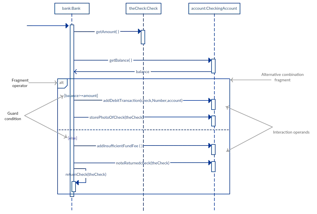
A sequence fragment is represented as a box that frames a section of interactions between objects (as shown in the examples below) in a sequence diagram. It is used to show complex interactions such as alternative flows and loops in a more structured way. On the top left corner of the fragment sits an operator. This fragment operator specifies what sort of a fragment it is.
Alternative Fragment
The alternative combination fragment is used when a choice needs to be made between two or more message sequences. It models the “if then else” logic. The alternative fragment is represented with a large rectangle or a frame; it is specified by mentioning ‘alt’ inside the frame’s name box (a.k.a. fragment operator). To show two or more alternatives, the larger rectangle is then divided into what are called ‘interaction operands’ using a dashed line, like shown in the sequence diagram example above. Each operand has a guard to test against and it is placed at the top left corner of the operand.
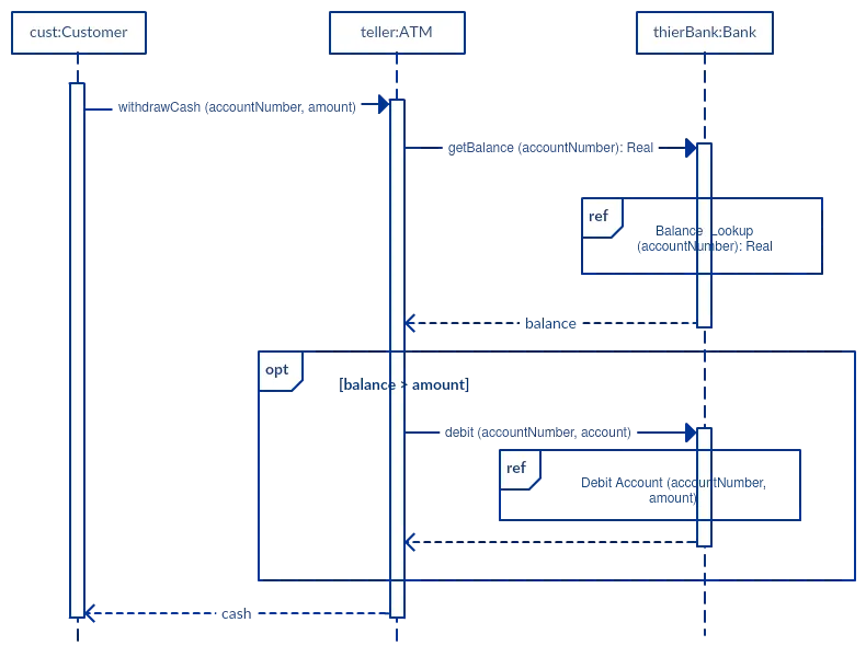
Option Fragment
The option combination fragment is used to indicate a sequence that will only occur under a certain condition, otherwise, the sequence won’t occur. It models the “if then” statement. Similar to the alternative fragment, the option fragment is also represented with a rectangular frame where ‘opt’ is placed inside the name box. Unlike the alternative fragment, an option fragment is not divided into two or more operands. Option’s guard is placed at the top left corner.
Loop Fragment
The loop fragment is used to represent a repetitive sequence. Place the words ‘loop’ in the name box and the guard condition near the top left corner of the frame. In addition to the Boolean test, the guard in a loop fragment can have two other special conditions tested against. These are minimum iterations (written as minint = [the number]) and maximum iterations (written as maxint = [the number]). If it is a minimum iterations guard, the loop must execute not less than the number mentioned, and if it is a maximum iterations guard, the loop mustn’t execute more than the number indicated.
Reference Fragment
You can use the ref fragment to manage the size of large sequence diagrams. It allows you to reuse part of one sequence diagram in another, or in other words, you can reference part of a diagram in another diagram using the ref fragment. To specify the reference fragment, you have to mention ‘ref’ in the name box of the frame and the name of the sequence diagram that is being referred to inside the frame.
For more on sequence fragments read Beyond the Basics of Sequence Diagrams Part 3.
Sequence Diagram Common Mistakes
When drawing sequence diagrams, designers tend to make these common mistakes. By avoiding these mistakes you can ensure the quality of your diagram.
- Adding too much detail. This clutters up the diagram and makes it difficult to read.
- Obsolete and out-of-date sequence diagrams that are irrelevant when compared to the interfaces, actual architectures, etc. of the system. Don’t forget to replace them or modify them.
- Leaving no blank space between the use case text and the message arrow; this makes it difficult for anyone to read the diagram.
- Not considering the origins of message arrows carefully.
Free UML Sequence Diagram Examples


FAQs on UML Sequence Diagrams
What are the benefits of sequence diagrams?
What makes sequence diagrams different from communication diagrams?
Can Sequence Diagrams represent conditional logic or loops?
How to show an “if” condition on a Sequence Diagram?
Use a UML fragment to represent conditional logic.
For a single “if–then” condition, use an opt fragment with the condition in brackets (e.g., [valid == true]).
For an “if–else” condition, use an alt fragment divided into sections for each possible outcome, each labeled with a guard condition (e.g., [success] / [failure]).
Resources
Al-Fedaghi, Sabah. “UML Sequence Diagram: An Alternative Model.” ArXiv.org, 31 May 2021, https://arxiv.org/abs/2105.15152.
Xiaoshan Li, et al. “A Formal Semantics of UML Sequence Diagram.” IEEE Xplore, 1 Apr. 2004, https://ieeexplore.ieee.org/abstract/document/1290469.


Ethan Brooks
How to correctly create a sequence diagram? Any suggestions?
Amanda Athuraliya
Start by identifying the participants (objects or actors) and arrange them horizontally. Then map the messages exchanged vertically in time order, using arrows with proper notation for synchronous or asynchronous calls. Use activation bars to show when an object is active, and keep the diagram clear by avoiding clutter like unnecessary return messages. Creately’s sequence diagram templates and shape libraries can help you visually organize and connect these elements efficiently.