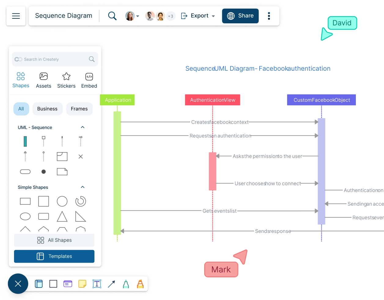
Sequence Diagram Tool
Tools, Templates and Resources to Draw Sequence Diagrams
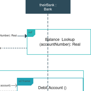
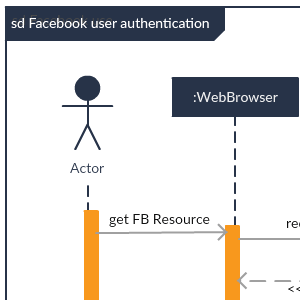
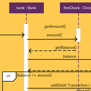
Sequence Diagram Templates


What Is a Sequence Diagram?
A sequence diagram is a UML diagram type that represents how and in what order objects in a system interact with each other.
Sequence Diagrams are used to design, document, and validate the architecture, interface and logic of systems by describing the sequence of actions that need to be performed to complete a task.
How to Create a Sequence Diagram?
Step 1: Identify the Actors and Objects
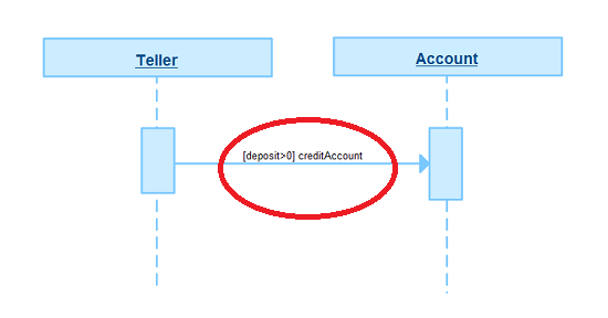
Start by identifying the actors and objects that will participate in the interaction. Actors represent external entities that interact with the system, such as users or other systems. Objects are the components within the system that will be interacting. In a sequence diagram, actors are represented by stick figures and objects are represented by rectangles.
Step 2: Define the Use Case
Clearly define the use case you are modeling. A use case describes a specific function or process within the system. Understanding the use case helps in identifying the sequence of interactions that need to be captured.
Step 3: Determine the Sequence of Events
Outline the sequence of events that occur during the interaction. This includes the messages exchanged between actors and objects. Think about the flow of control and how each message triggers subsequent actions.
Step 4: Create Lifelines for Actors and Objects
Create lifelines for each actor and object. Lifelines are vertical dashed lines that represent the existence of an object over time. Place the actors on the left side and the objects on the right side of the diagram.
Step 5: Add Messages
Add messages between the lifelines to represent the interactions. Messages are arrows that indicate the flow of information or control between actors and objects.
- Use messages (a solid line) to indicate a request or an information transmission.
- Use a return message (dashed line) to indicate a response to a message.
- Use a self message (return arrow) to indicate a repetitive call of an operation or to represent one method calling another method of the same object.
- Use an asynchronous message (open arrowhead) to indicate an instance when an action might not take place immediately.
Step 6: Include Activation Bars
Activation bars, also known as focus of control, are thin rectangles on lifelines that show when an object is active or performing an action. They help visualize the duration of an object’s activity during the interaction.
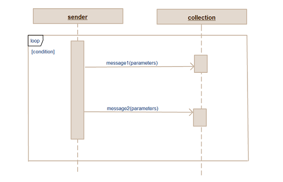
Step 7: Incorporate Conditions and Loops
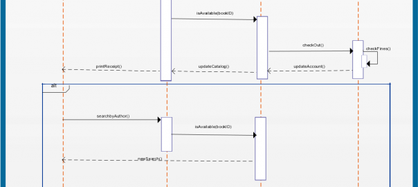
If your interaction includes conditional logic or loops, use fragments to represent these scenarios. Fragments are boxes that enclose parts of the diagram and are labeled with the type of interaction, such as “alt” for alternatives or “loop” for loops.
Step 8: Review and Refine
Review your sequence diagram to ensure it accurately represents the interaction. Check for completeness and clarity. Make any necessary adjustments to improve readability and accuracy.
How to Read a Sequence Diagram?
Understanding the Components of a Sequence Diagram
A UML sequence diagram captures the interaction between objects in the context of a collaboration. Following are the main components of sequence diagrams.
Lifelines: Represent the participants in the interaction. Each lifeline is depicted as a vertical dashed line. Messages: Arrows between lifelines represent the messages exchanged between the participants. Activation Bars: Thin rectangles on lifelines indicate when an object is active or executing a process.
Reading the Flow
The flow of the diagram is top-down. The sequence of messages starts at the top and moves downward, showing the order of interactions.
Synchronous Messages: Represented by a solid arrowhead, indicating that the sender waits for the receiver to process the message.
Asynchronous Messages: Indicate that the sender does not wait for the receiver to process the message. Consider an online shopping system. A customer (lifeline) sends a request to the server (another lifeline) to view product details. The server processes this request (activation bar) and sends back the product information (message). This simple interaction can be expanded to include payment processing, order confirmation, and more.
Sequence Diagram Articles
FAQs about the Sequence Diagram Tool in Creately
How do I generate a PDF of my sequence diagram?
To generate a PDF of your sequence diagram in Creately, follow these steps:
- Create or open your sequence diagram in Creately.
- Click on the ‘Export’ button on the toolbar on the top left.
- Select ‘Export as PDF’ from the export options.
- Your diagram will be saved in Downloads.
Are there any example sequence diagrams?
Yes, Creately offers a variety of example sequence diagrams that you can use as templates or for inspiration. Some examples include:
- ATM system sequence diagram
- Sequence Diagram for Student registration system
- Sequence Diagram for Online shopping system
- User registration sequence diagram
These examples can be easily edited and customized to fit your specific needs.
Which tool is used for sequence diagrams?
What makes a good sequence diagram?
- A good sequence diagram should have the following characteristics:
- The diagram should be easy to understand, with clear and descriptive names for lifelines and messages.
- Avoid unnecessary complexity by focusing on key interactions and relationships.
- Ensure that the sequence of interactions is accurately represented.
- Use standard UML notations and maintain a consistent style throughout the diagram.
- Include all relevant actors, objects, messages, and interactions to provide a complete picture of the system’s behavior.