Deployment diagrams are used to visualize the hardware processors/ nodes/ devices of a system, the links of communication between them and the placement of software files on that hardware.
In this UML deployment diagram tutorial, we will cover what is a deployment diagram, deployment diagram notations and how to draw one. You can use one of the editable deployment diagram examples to start right away.
If you are deploying to the cloud, you may skip UML altogether and use something like our AWS architecture templates to achieve the same purpose.
What is Deployment Diagram
A deployment diagram is a UML diagram type that shows the execution architecture of a system, including nodes such as hardware or software execution environments, and the middleware connecting them.
Deployment diagrams are typically used to visualize the physical hardware and software of a system. Using it you can understand how the system will be physically deployed on the hardware.
Deployment diagrams help model the hardware topology of a system compared to other UML diagram types which mostly outline the logical components of a system.
Deployment Diagram Notations
In order to draw a deployment diagram, you need to first become familiar with the following deployment diagram notations and deployment diagram elements.
Nodes

A node, represented as a cube, is a physical entity that executes one or more components, subsystems or executables. A node could be a hardware or software element.
Artifacts

Artifacts are concrete elements that are caused by a development process. Examples of artifacts are libraries, archives, configuration files, executable files etc.
Communication Association

This is represented by a solid line between two nodes. It shows the path of communication between nodes.
Devices
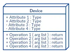
A device is a node that is used to represent a physical computational resource in a system. An example of a device is an application server.
Deployment Specifications
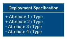
Deployment specifications is a configuration file, such as a text file or an XML document. It describes how an artifact is deployed on a node.
How to Draw a Deployment Diagram
Follow the simple steps below to draw a deployment diagram. You can either use the deployment diagram examples below to get a head start or use our UML diagram tool to start from the beginning.
Step 1: Identify the purpose of your deployment diagram. And to do so, you need to identify the nodes and devices within the system you’ll be visualizing with the diagram.
Step 2: Figure out the relationships between the nodes and devices. Once you know how they are connected, proceed to add the communication associations to the diagram.
Step 3: Identify what other elements like components, active objects you need to add to complete the diagram.
Step 4: Add dependencies between components and objects as required.
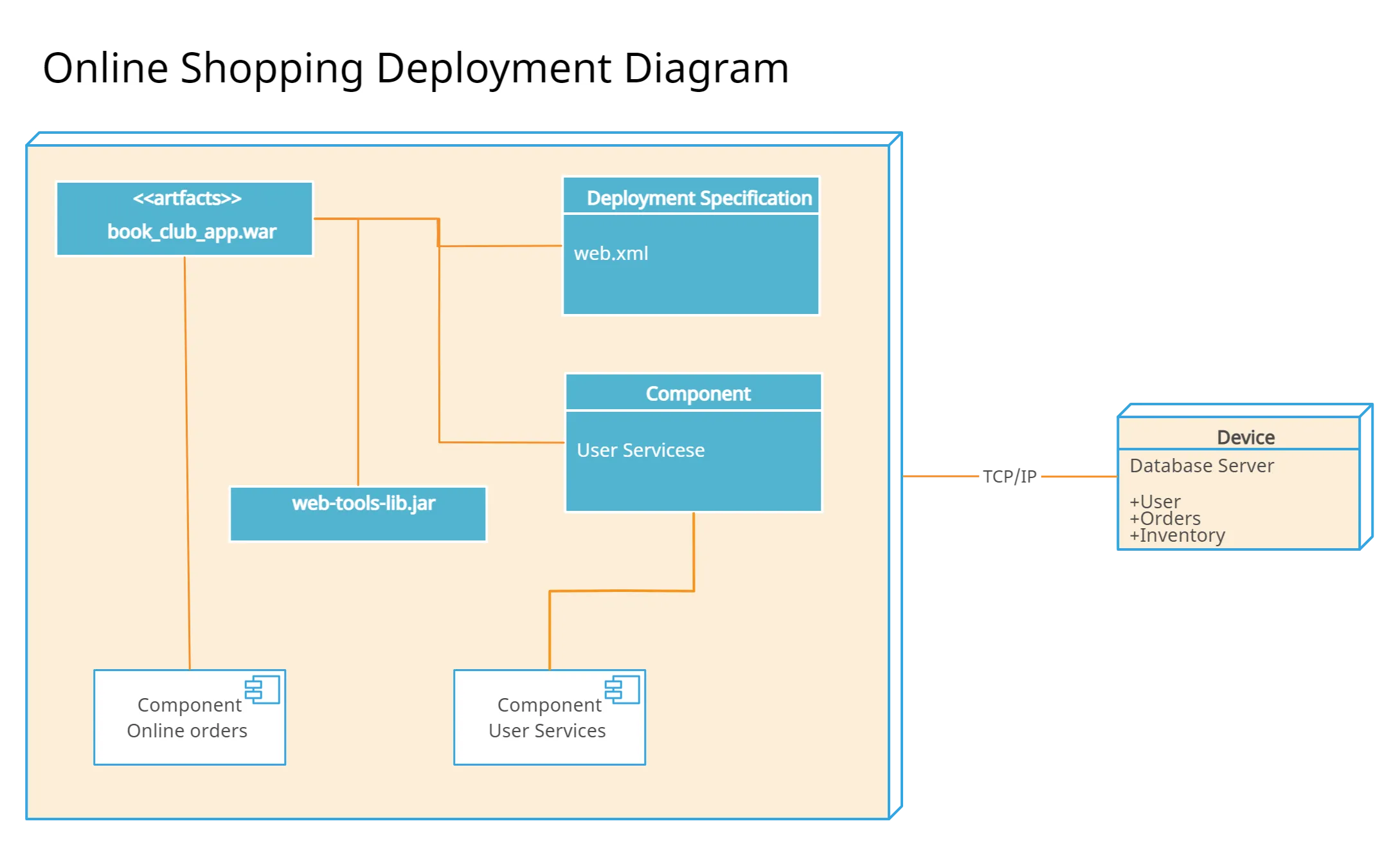
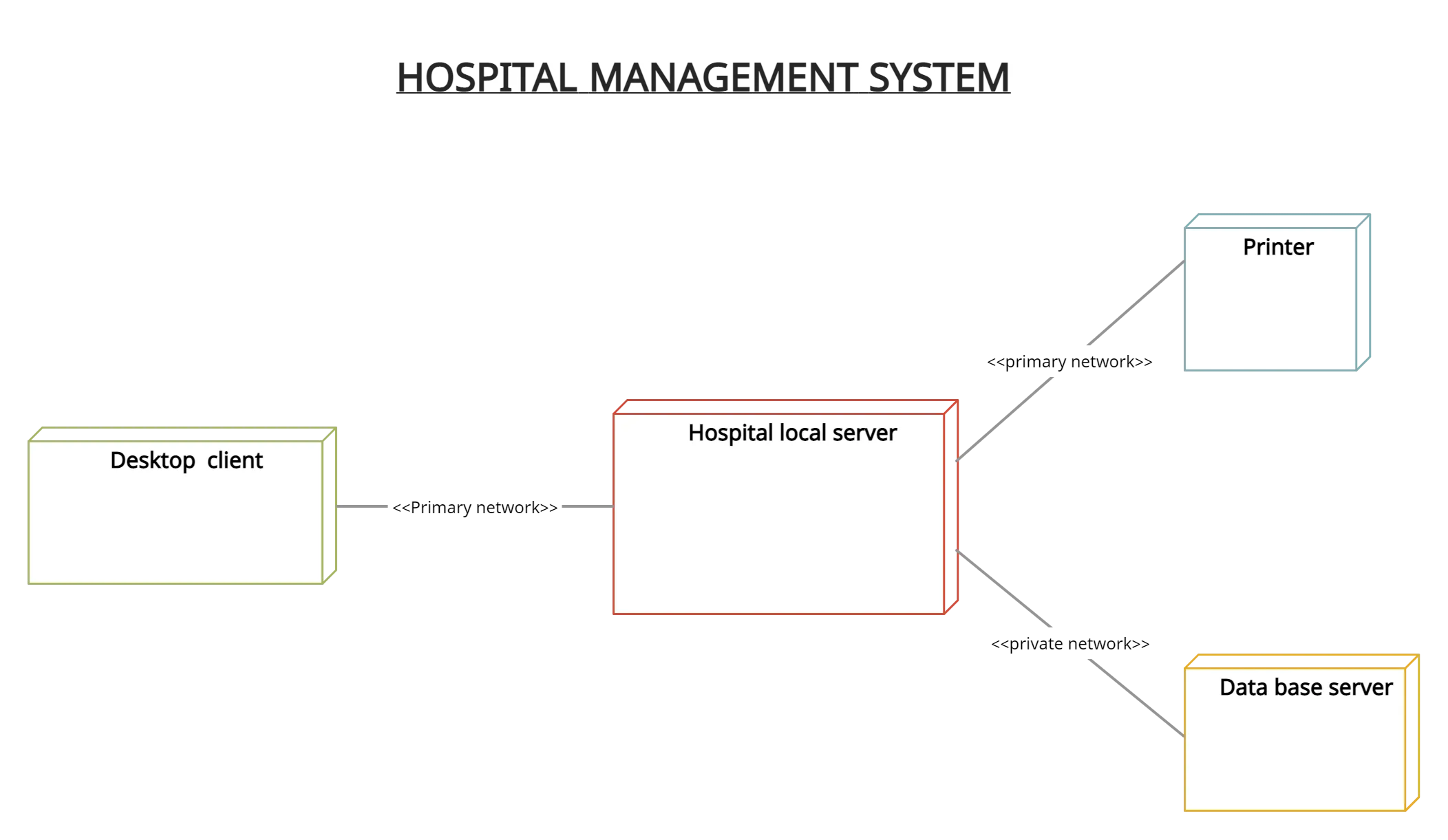
Deployment Diagram Examples
Deployment Diagram for Online Shopping System
Deployment Diagram for Library Management System

Deployment Diagram for Hospital Management System
Deployment Diagram for Hotel Management System

Share the Deployment Diagram Tutorial
In this deployment diagram tutorial, we have covered everything you need to know – from what is a deployment diagram to deployment diagram elements – to draw a deployment diagram yourself. Use our UML diagram tool for powerful features that’ll make drawing UML diagrams easier.
Last week we published a comprehensive tutorial on component diagrams and if you missed it, do check it out below with our other UML diagram tutorials.
The Easy Guide to Component Diagrams The Easy Guide to Activity Diagrams The Easy Guide to Class Diagrams The Ultimate Guide to Sequence Diagram TutorialsAnd don’t forget to leave your thoughts in the comment section below.
FAQs About UML Deployment Diagrams
Deployment diagrams are typically used by software developers, system architects, and IT professionals who are responsible for designing and deploying software systems. They are particularly useful in large-scale applications where multiple software components must be deployed across multiple servers or machines.
Deployment diagrams are also useful in the early stages of software development, where they can help to identify potential performance bottlenecks or other issues that may arise when deploying software components into a production environment.
System architects and IT specialists can benefit from deployment diagrams because they give a visual representation of how software components are distributed in a real-world setting. Here are some specific applications for deployment diagrams:
Architecture and IT experts can use deployment diagrams to plan and construct the physical foundation of a software system. They can see potential performance bottlenecks, network congestion, and other problems that can occur when installing the system by visualizing the distribution of software components.
Communication: Developers, project managers, and business stakeholders can all receive the architecture of a software system using deployment diagrams. Architects and IT specialists can make sure that everyone working on the project has a clear knowledge of how the system will be deployed by adopting a common notation like UML.
Deployment diagrams can also be used to test and troubleshoot software systems in real-world settings. IT experts can visualize the deployment of software components, allowing them to spot possible problems before they occur and take action to fix them.
Deployment diagrams can also assist architects and IT specialists in making plans for the upkeep and scalability of a software system. They can find potential weak points and take action to make sure the system is scalable and can manage growing quantities of traffic or data by understanding how software components are deployed in a production environment.
Creating a deployment diagram can be a complex process, and there are several common mistakes that people make when creating them. Here are some mistakes to avoid when creating deployment diagrams:
Lack of clarity: One common mistake is creating a deployment diagram that is difficult to read or understand. To avoid this, it is important to use clear and concise labels for each element in the diagram, and to ensure that the relationships between elements are clearly defined.
Inaccurate mapping: Another mistake is mapping software components to the wrong physical hardware or network components. To avoid this, it is important to carefully review the architecture of the system and ensure that each component is accurately mapped to the appropriate hardware or network element.
Overcomplicating the diagram: Sometimes, deployment diagrams can become too complex, making them difficult to understand. To avoid this, it is important to keep the diagram as simple as possible, focusing on the most important components and relationships.
Ignoring security and privacy: Another mistake is ignoring security and privacy concerns when creating a deployment diagram. It is important to consider the security and privacy implications of each component and relationship in the diagram, and to ensure that appropriate security measures are in place to protect sensitive data.
Not keeping the diagram up to date: Finally, it is important to keep the deployment diagram up to date as changes are made to the system. Failure to do so can result in an outdated diagram that is no longer accurate, leading to confusion and potential errors.


