While other UML diagrams, which describe the functionality of a system, component diagrams are used to model the components that help make those functionalities.
In this component diagram tutorial, we will look at what a component diagram is, component diagram symbols, and how to draw one. You can use a component diagram example below to get a quick start.
UML Component Diagram Definition
A component diagram is a type of UML diagram used to visualize the high-level structure of a system by showing its components and the relationships between them. Unlike class diagrams that focus on the behavior and attributes of classes, component diagrams highlight how the system is divided into modular parts and how these parts interact through interfaces.
Purpose of a Component Diagram
- Visualize system structure: Provides a clear overview of all major components and their connections.
- Highlight dependencies: Shows how components rely on each other through provided and required interfaces.
- Support system design: Helps developers and architects plan component-based or service-oriented architectures.
- Communicate with stakeholders: Offers a simplified view of complex systems for non-technical stakeholders.
Use Cases
Component diagrams are widely used in software, hardware, and business system modeling:
- Software components: Represent modules like a database, user interface, authentication service, or payment gateway.
- Hardware components: Model physical elements such as microchips, network devices, or circuit boards that support system functions.
- Business components: Show organizational units like payroll, logistics, or supplier management that interact within a business process.
By mapping these components, teams can identify potential bottlenecks, simplify system maintenance, and plan scalable architectures effectively.
Component Diagram Symbols
Component diagrams use specific symbols to represent system elements and their relationships. Understanding these symbols is key to creating clear and accurate diagrams.
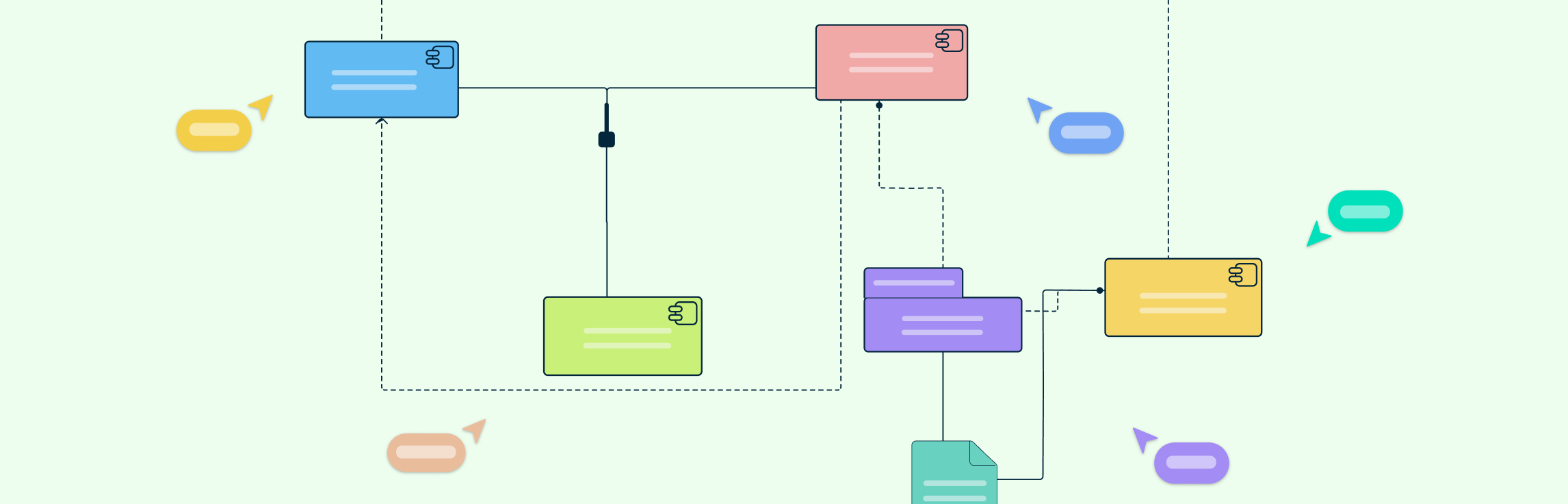
Component
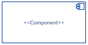
The component symbol represents a modular part of the system that encapsulates its functionality. There are three ways the component symbol can be used.
Notation 1:
Rectangle with the component stereotype (the text <<component>>). The component stereotype is usually used above the component name to avoid confusing the shape with a class icon.
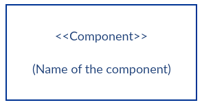
Notation 2:
Rectangle with the component icon in the top right corner and the name of the component.
Notation 3:
A rectangle with both the component icon and the stereotype label.
Components can represent software modules, hardware units, or business services, depending on the system being modeled.
Provided Interface and the Required Interface
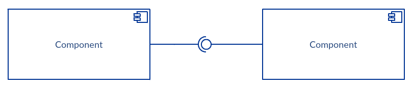
Interfaces in component diagrams show how components are wired together and interact with each other.
- Provided interface: Represented by a circle, it indicates a service offered by a component.
- Required interface: Represented by a half-circle (semi-circle), it indicates a service the component needs from another.
- Assembly connector: Connects a component’s required interface to another component’s provided interface, showing dependency and interaction.
Port
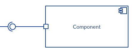
A port is a small square on the edge of a component, used to delegate interfaces to internal classes or subcomponents. Ports help organize interactions, especially in large or complex systems, and clarify which component handles which interface.
Dependencies
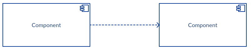
Dependencies indicate that one component relies on another.
- Shown using a dashed arrow, dependencies can complement interface connections.
- For detailed interactions, the ball-and-socket notation (provided and required interfaces) can be used.
How to Draw a Component Diagram
Creating a component diagram helps visualize system components and their interactions. Follow these steps to design one efficiently using UML principles.
Step 1: Define the Purpose and Scope
Before drawing, clarify what you want to represent and which components are relevant.
- Identify artifacts such as files, modules, services, or business units.
- Decide the level of detail needed, high-level overview or detailed component interactions.
Tip: Keep your diagram focused; including too many components can make it cluttered.
Common Mistake: Skipping this step may result in a diagram that is confusing or incomplete.
Step 2: Identify Components
List all components required for your system, including software, hardware, and business units.
- Group related components logically to make the diagram readable.
Tip: Use consistent naming for each component to avoid confusion.
Step 3: Map Interfaces
Determine which components provide or require services from others.
- Add provided interfaces (circles) and required interfaces (semi-circles).
- Connect interfaces using assembly connectors to indicate interactions.
Tip: Clearly distinguish between provided and required interfaces for accuracy.
Common Mistake: Forgetting to link interfaces can misrepresent component relationships.
Step 4: Add Ports and Dependencies
Include ports for internal delegation and dependency arrows for additional relationships.
- Ports help show how components interact with internal classes or subcomponents.
- Dependencies clarify which components rely on others even without explicit interfaces.
Tip: Only show essential dependencies to avoid clutter.
Step 5: Review and Annotate
Check your diagram for completeness and readability.
- Add notes or labels to clarify complex interactions.
- Ensure consistent use of symbols throughout the diagram.
Tip: Use colors or grouping boxes to visually separate logical modules for clarity.
Common Mistake: Leaving the diagram unlabeled or inconsistent can confuse stakeholders.
Benefits of Component Diagrams
A component diagram offers more than just a visual overview — it helps teams design, communicate, and maintain complex systems efficiently. Below are the key benefits of using component diagrams in UML-based system design.
Visualization of System Architecture
Component diagrams provide a clear visual representation of the system’s architecture, including its components, interfaces, and dependencies. This bird’s-eye view helps teams quickly understand how different modules interact and where potential bottlenecks or integration points exist.
Modularity and Reusability
By breaking down complex systems into smaller, reusable modules, component diagrams promote modularity in software and system design. This approach allows developers to reuse existing components across different projects, saving time and improving consistency.
Improved Communication
Component diagrams establish a common visual language that bridges communication gaps between project managers, developers, architects, and testers. They make technical details easier to grasp, ensuring that all stakeholders share a unified understanding of the system’s structure.
Ease of Maintenance and System Evolution
Because component diagrams document the system’s structure and dependencies, they make it easier to update or maintain systems over time. When teams need to modify a module or add new functionality, they can instantly see how those changes affect other components.
Enforcement of Design Principles
Component diagrams encourage adherence to key design principles such as encapsulation, cohesion, and loose coupling. By visually depicting how components interact through interfaces, they help ensure that each module remains self-contained and easy to integrate or replace.
Component Diagram Examples
Below are practical component diagram examples for common systems. You can instantly edit these templates online in Creately to visualize your own components and their interactions.
Component Diagram for Library Management System
This diagram models the major components of a library system, including catalog management, user interface, lending service, and database. It helps visualize how users interact with the system and how different services are connected. By understanding these relationships, developers and administrators can improve efficiency and identify potential bottlenecks. This template provides a clear starting point for designing or documenting a library management system.
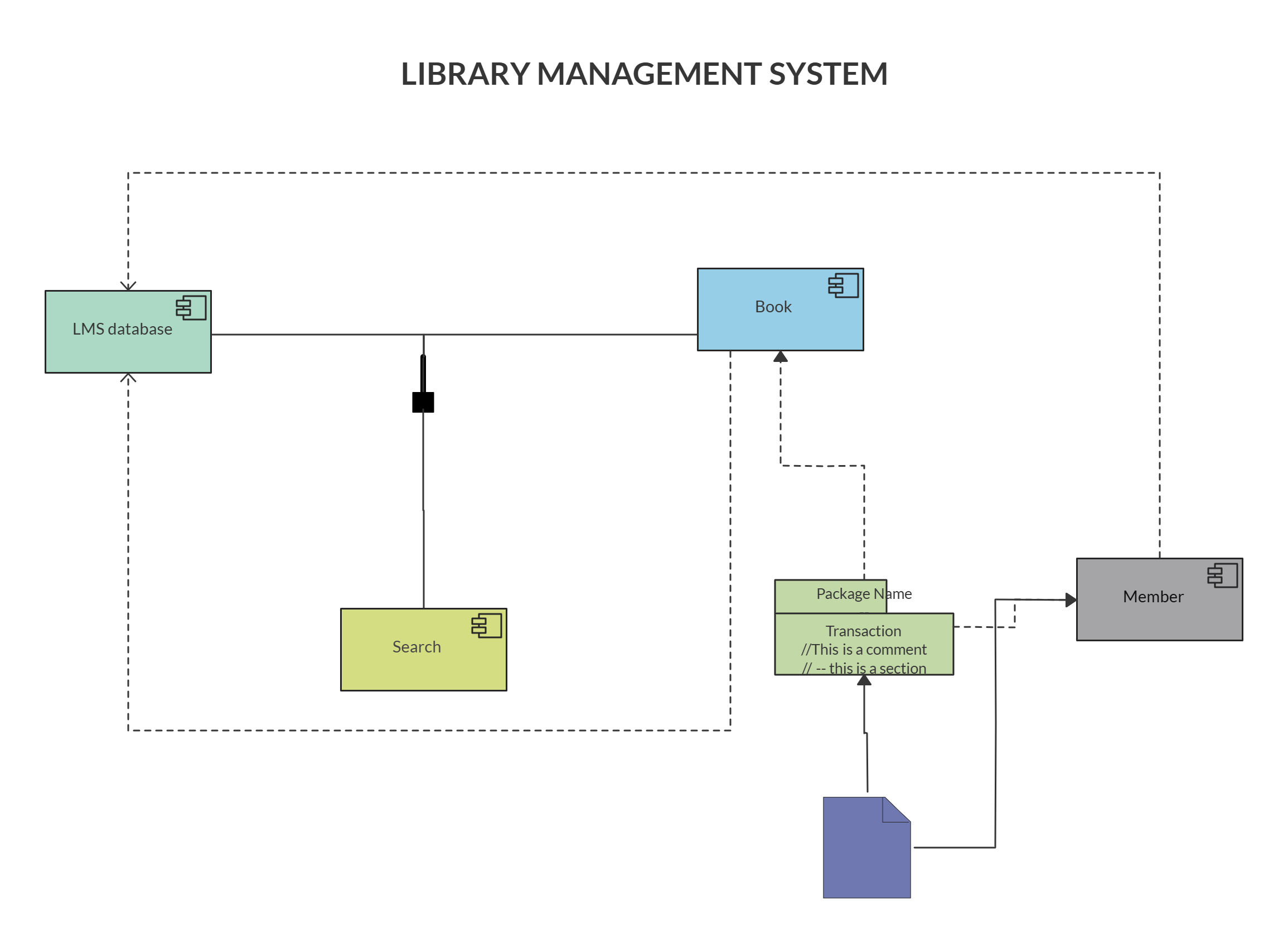
Component Diagram for Library Management System
Component Diagram for Online Shopping System
This template maps essential components of an e-commerce system, such as the shopping cart, payment gateway, product catalog, and user authentication. It shows how each module interacts to provide a seamless shopping experience for users. The diagram highlights dependencies between services, helping teams plan integration and troubleshooting. Use this template to quickly create a robust and maintainable online shopping architecture.
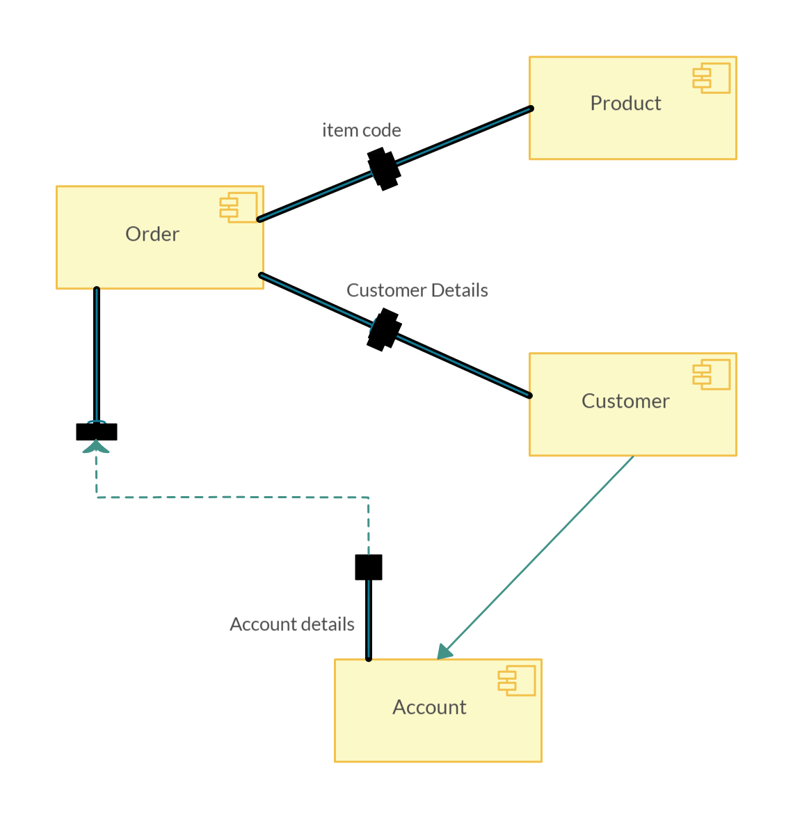
Component Diagram for Online Shopping System
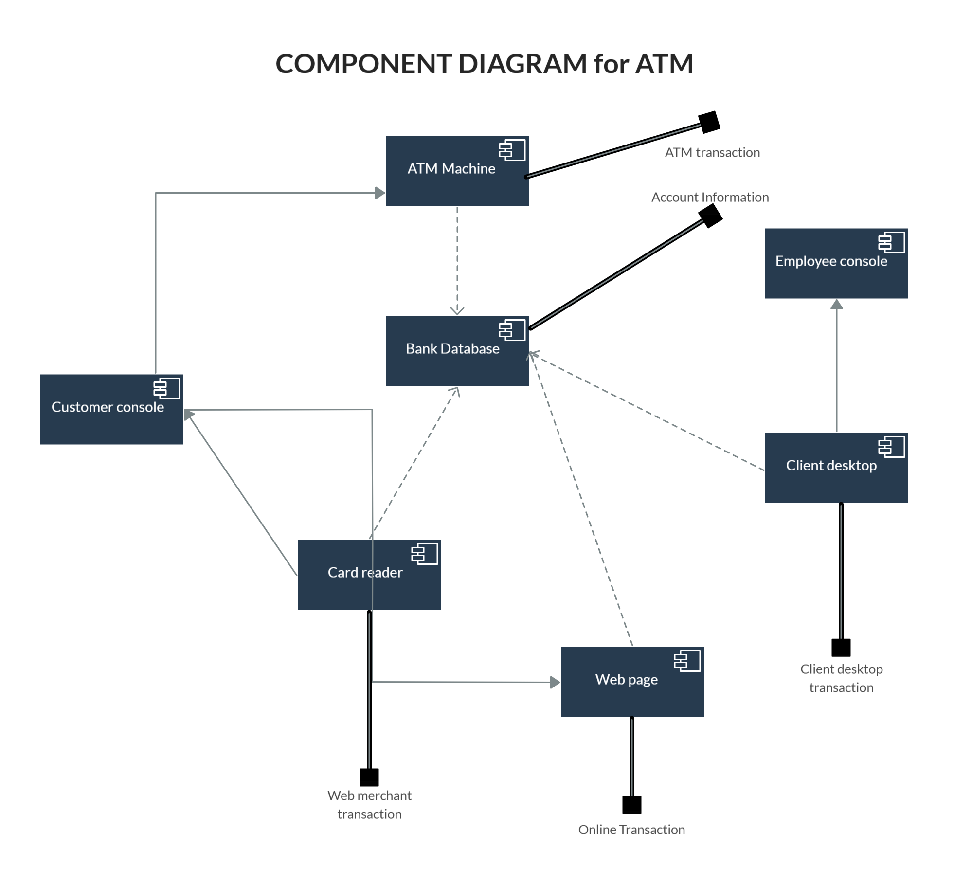
Component Diagram for ATM
This component diagram illustrates the ATM system’s core modules, including the card reader, transaction processor, user interface, and bank database. It helps identify how each component communicates with the others to complete banking transactions safely. The diagram is useful for both software developers and banking system analysts to understand workflow and security considerations. This template provides a practical visual reference for designing or documenting ATM systems.
Component Diagram for Hospital Management System
This diagram shows the main components of a hospital management system, including patient management, pharmacy, billing, and staff modules. It helps visualize interactions between clinical and administrative services to ensure smooth operations. The diagram can be used to identify process inefficiencies and improve system communication. Use this template as a guide to map complex hospital workflows clearly and effectively.
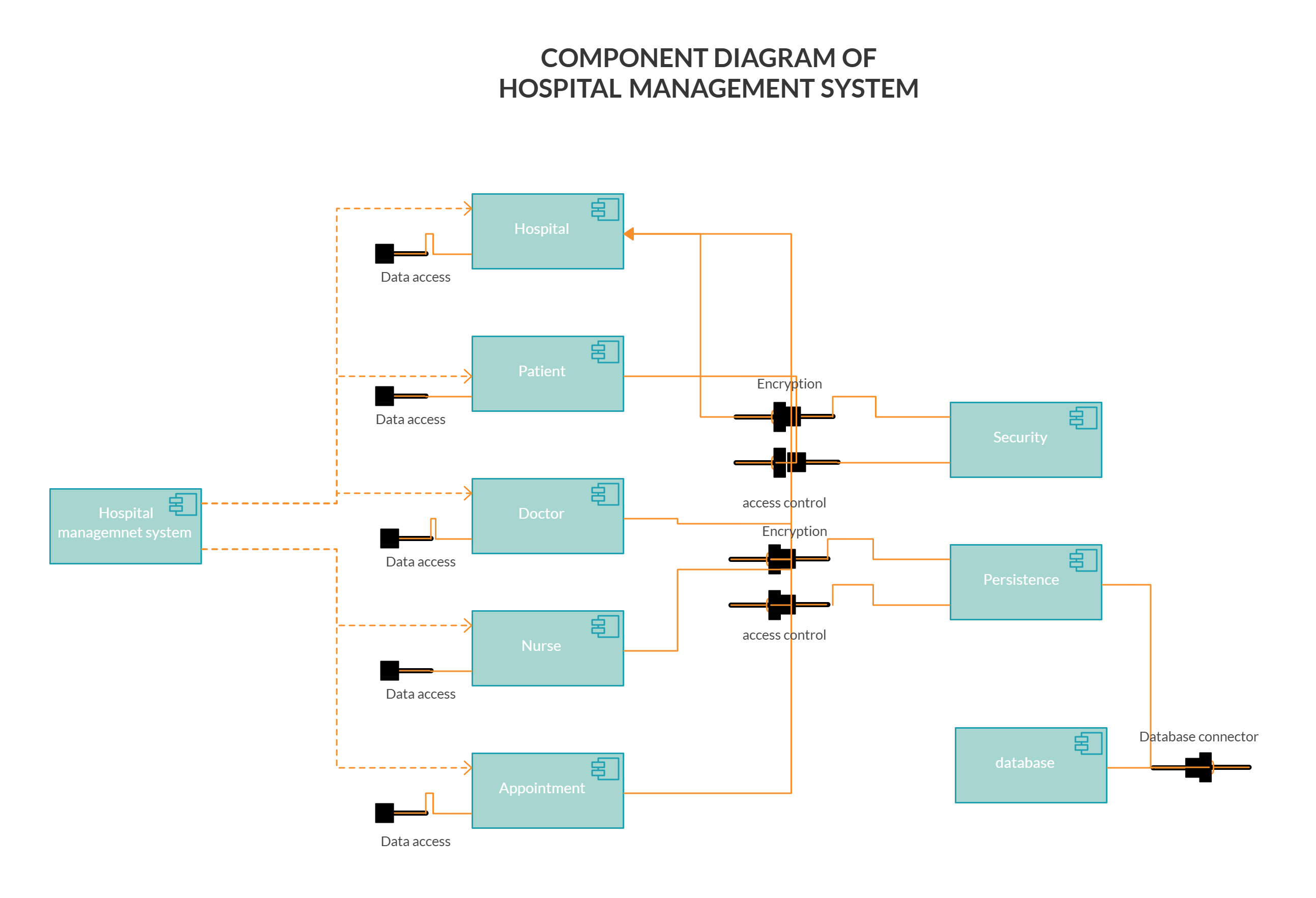
Component Diagram for Hospital Management System
Component Diagram for Inventory Management System
This template represents key components of an inventory management system, including stock tracking, order processing, supplier interface, and reporting modules. It highlights how different modules communicate to maintain accurate inventory levels and streamline operations. The diagram helps teams plan system architecture and understand dependencies between services. This example provides a strong foundation for designing or documenting inventory systems efficiently.
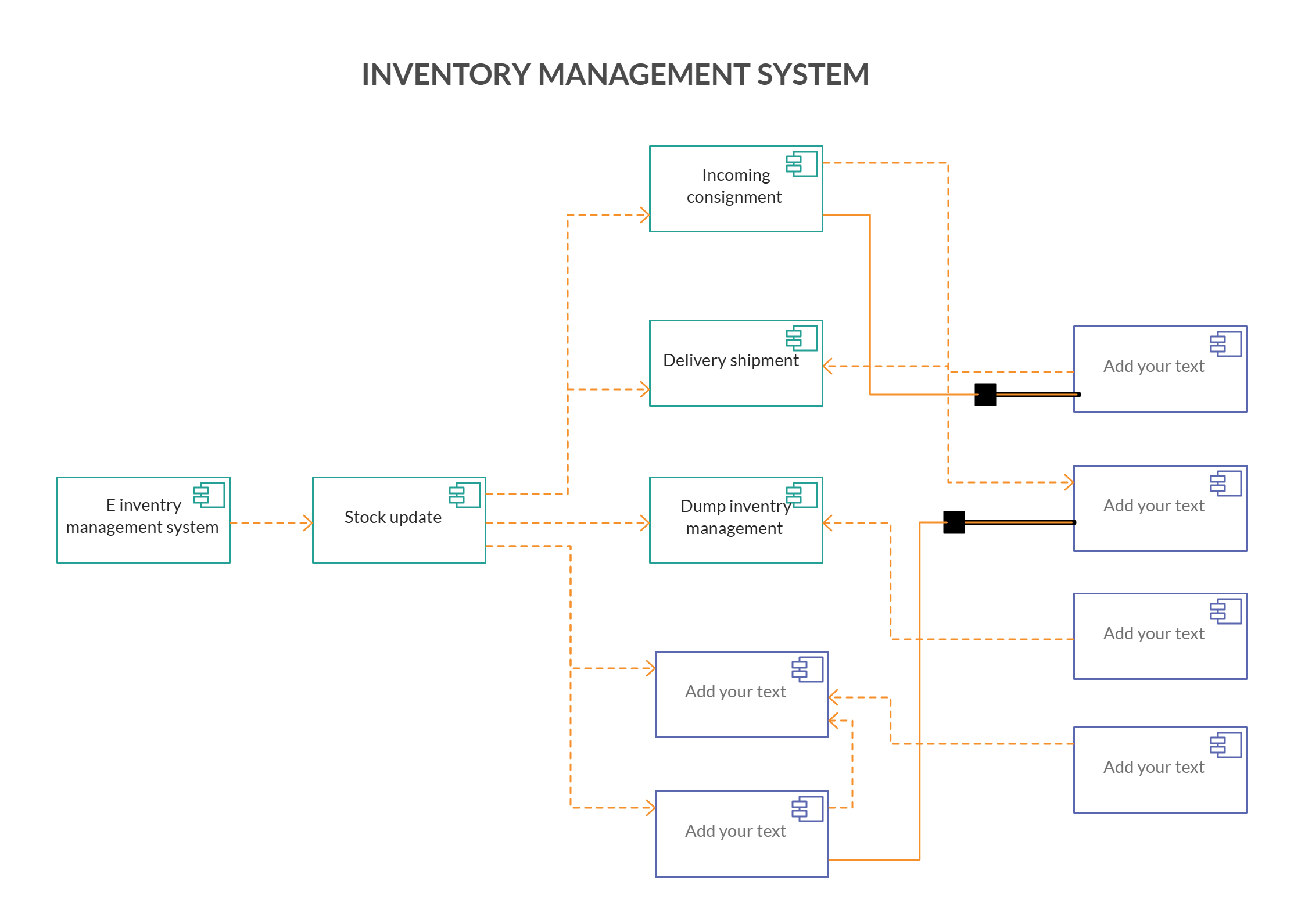
Component Diagram for Inventory Management System
What are Your Thoughts on the Component Diagram Tutorial
In this component diagram tutorial, we’ve covered everything you need to know about component diagrams to easily draw one. You can use our UML diagram creator to draw component diagram online.
We recently published guides on UML activity diagrams and class diagrams as well, and if you missed out here are the links;
The Easy Guide to Class Diagrams
The Easy Guide to Activity Diagrams
Don’t forget to let us know your thoughts in the comment section below.
FAQs About Component Diagrams
1. What is the difference between a class diagram and a component diagram?
A class diagram focuses on the internal structure of classes, their attributes, methods, and relationships. In contrast, a component diagram shows high-level modules (components) and their interactions through interfaces, emphasizing system architecture rather than implementation details. Use class diagrams for software design and component diagrams for system organization.
2. Can component diagrams show both software and hardware components?
Yes, component diagrams can represent software modules, hardware devices, or even business services. This makes them versatile for visualizing systems that combine code, infrastructure, and organizational units, providing a clear picture of how all components interact.
3. How do provided and required interfaces work in a component diagram?
Provided interfaces (circles) represent services a component offers, while required interfaces (semi-circles) represent services a component needs. Components are connected using assembly connectors, which indicate which services are supplied and consumed between components.
4. Are component diagrams only used in UML?
While component diagrams are part of UML (Unified Modeling Language), their concepts can be applied in other modeling techniques. However, UML provides standardized symbols and conventions, making diagrams easier to understand and share across teams.
5. What are some common mistakes when drawing component diagrams?
- Including too many components makes the diagram cluttered.
- Failing to distinguish clearly between provided and required interfaces.
- Using inconsistent naming for components or interfaces.
- Skipping annotations or notes for complex interactions.
6. When should I use a component diagram?
Use component diagrams when you need to visualize the system’s modular structure, communicate high-level dependencies, or plan component-based development. They are particularly useful in service-oriented architectures (SOA), large-scale applications, and systems with multiple interacting modules.