We basically looked into and covered the basics of sequence diagrams last week. This should be enough information when it comes to modeling most of the interactions that will take place in a common system. At this juncture, the natural route to take would be to look into more deeper aspects of sequence diagrams. What we will be looking at would be to cover more advanced notation elements that can be used in such diagrams. However, since this is bound to be rather detailed, this will be the first part of more advanced elements of Sequence Diagrams.
How to reference another Sequence Diagram
As most of you may know interaction occurrences are an important part of UML 2. Interaction occurrences help in the instance of enabling the chance to create basic sequence diagrams into ones which are more complicated. The proper way in which to put out an interaction occurrence element is by using a frame. The text “ref” is put inside the frame’s namebox, while the name of the sequence diagram that is being referenced is put inside the frame’s content area along with any parameters to the diagram. The notation of the sequence diagram is as follows:
sequence diagram name[(arguments)] [: return value]
Two examples:
Example 1. Retrieve Borrower Credit Report(ssn) : borrowerCreditReport
or
Example 2. Process Credit Card(name, number, expirationDate, amount : 100)
When it comes to example 1, the syntax calls the sequence diagram called Retrieve Borrower Credit Report and passes it the parameter ssn. The Retrieve Borrower Credit Report sequence returns the variable borrower CreditReport. In example 2, the syntax calls the sequence diagram called Process Credit Card and passes it the parameters of number, name, amount, and expiration date. However, in example 2 the amount parameter will be a value of 100. And since example 2 does not possess a return value labeled, the sequence will not return a value.
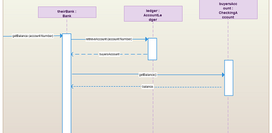
Figure 1 shows a sequence diagram that references the sequence diagrams “Balance Lookup” and “Debit Account.” The sequence starts at the top left, with the customer sending a message to the teller object. The teller object sends a message to the theirBank object. At that point, the Balance Lookup sequence diagram is called, with the accountNumber passed as a parameter. The Balance Lookup sequence diagram returns the balance variable. Then the option combination fragment’s guard condition is looked into to gauge if the balance is greater than the amount variable. In such cases, the Debit Account sequence diagram is called, passing it the accountNumber and the amount as parameters. After that sequence is complete, the withdrawCash message returns cash to the customer.
It is important to notice in Figure 1 that the lifeline of theirBank is hidden by the interaction occurrence Balance Lookup. Since the interaction occurrence hides the lifeline, this means that the theirBank lifeline is referenced in the “Balance Lookup” sequence diagram. While the lifeline in the interaction occurrence is being hidden, UML 2 also indicates that the lifeline must have the same theirBank in its own “Balance Lookup” sequence. There will be instances when you model sequence diagrams where an interaction occurrence will overlap lifelines, which are not referenced in the interaction occurrence. In such cases the lifeline is shown as a normal lifeline and is not hidden by the overlapping interaction occurrence.
In Figure 1, the sequence references the “Balance Lookup” sequence diagram. The “Balance Lookup” sequence diagram is shown in Figure 2. Because the example sequence has parameters and a return value, its label —located in the diagram’s namebox—follows a specific pattern:
Diagram Type Diagram Name [(Parameter Type : Parameter Name)] :
[: Return Value Type]
The example – SD Balance Lookup(Integer : accountNumber) : Real
Figure 2 illustrates example 1, in which the Balance Lookup sequence uses parameter accountNumber as a variable in the sequence, and the sequence diagram shows a Real object being returned. In cases such as this, where the sequence returns an object, the object being returned is given the instance name of the sequence diagram.
With that wrapping up today’s post, stay tuned for Part 2 within the course of this week!
Also check out this complete Sequence Diagram Tutorial to learn more about sequence diagrams.


[…] got the final part of this series right here. While we did spend some time discussing Gates and its use or relevance to Sequence […]
[…] wrap up the week with where we left off with Sequence Diagrams and a look into more advanced elements. Today we will concentrate on the use of Gates in Sequence […]