Cisco network topology diagrams play a critical role in how modern networks are designed, managed, and explained. For network engineers and IT teams working with Cisco environments, a clear visual layout of devices and connections makes it easier to plan architectures, communicate designs, and troubleshoot issues faster. In this guide, you’ll learn how to approach Cisco network topology diagrams with confidence and create visuals that are practical, accurate, and easy to understand.
What Is a Cisco Network Topology Diagram
A Cisco network topology diagram is a visual map that shows how all the major pieces of a Cisco-based network fit and work together — from routers and switches to firewalls, access points, and links between them. These diagrams aren’t just drawings; they help you see both the physical layout (where devices and cables actually sit) and the logical flow (how data moves between devices) of your network, making complex systems easier to understand and manage.
For network teams, having a clear topology is essential for planning, troubleshooting, documenting changes, and communicating network architecture to colleagues or stakeholders. By laying out nodes and connections in a standardized way, Cisco topology diagrams help you spot issues faster, design for performance and redundancy, and keep your infrastructure aligned with business needs.
Why Cisco Network Topology Diagrams Matter
Cisco network topology diagrams aren’t just visual aids — they are essential tools for network engineers and administrators. They help teams understand, manage, and optimize complex networks efficiently.
Key benefits
Clear documentation: Keep track of every device, link, and connection. This makes audits, compliance, and change tracking much easier.
Faster troubleshooting: Trace paths, isolate faults, and identify misconfigurations without guessing or digging through configs.
Smarter planning and upgrades: Visualize how new devices or segments will integrate into your network and spot potential bottlenecks before changes are implemented.
Knowledge sharing: Makes it easier to onboard new team members and communicate network design across teams.
Cisco-specific context
Topology diagrams are integral to Cisco environments and professional training (CCNA, CCNP).
Engineers learn to map both physical layouts (devices, ports, cabling) and logical flows (VLANs, subnets, routing paths).
These diagrams ensure network designs follow best practices and remain reliable over time.
With a clear topology diagram, teams gain a bird’s-eye view of the network, helping them act faster, make smarter decisions, and reduce downtime.
When to Use a Cisco Topology Diagram
Cisco topology diagrams are more than just planning tools — they’re essential for keeping networks organized, efficient, and resilient. Knowing when to use them ensures you get maximum value from your diagrams.
1. Network Planning and Design
Before deploying new devices or expanding your network, topology diagrams help you:
Visualize how new routers, switches, or access points will fit into the existing network
Identify potential bottlenecks or single points of failure
Plan for scalability and redundancy
2. Troubleshooting and Issue Resolution
When network problems occur, a diagram acts like a roadmap:
Trace traffic flow and identify misconfigurations quickly
Isolate faults in complex networks without guessing
Reduce downtime and speed up resolution
3. Documentation and Compliance
Topology diagrams serve as a reliable record of your network:
Maintain up-to-date documentation for audits or regulatory compliance
Help new team members understand the network quickly
Track changes over time and align physical infrastructure with logical design
4. Network Upgrades and Migration
When upgrading hardware or migrating to new architectures:
Assess how new devices will integrate with existing infrastructure
Visualize dependencies between routers, switches, firewalls, and VLANs
Minimize risks during deployment by planning visually
5. Training and Knowledge Sharing
Diagrams are excellent teaching and communication tools:
Explain network design to non-technical stakeholders
Onboard new engineers efficiently
Share best practices in team meetings or training sessions
Components of a Cisco Network Topology
In Cisco network topology diagrams, every symbol and connection tells a story. Knowing the key components helps you build clear diagrams that reflect real‑world networks — and makes troubleshooting and planning easier.
| Component | Description | Cisco Examples / Notes |
| Routers | Direct traffic between different networks and determine the best path for data. | Cisco ISR, ASR series; handle WAN and inter-subnet routing. |
| Switches | Connect devices within the same network; can be access or multi-layer. | Cisco Catalyst, Nexus series; used for LAN, VLANs, and routing. |
| Firewalls | Enforce security policies and control traffic between network segments. | Cisco ASA, Firepower; placed at network edge or between segments. |
| Wireless Access Points (APs) | Provide Wi-Fi connectivity and link wireless devices to the network. | Cisco Aironet, Catalyst APs; managed via controllers. |
| Controllers & Gateways | Centralize management of wireless networks or WAN traffic. | Cisco Wireless LAN Controller, WAN gateway devices. |
| Ethernet Links | Physical connections using cables to connect devices. | Cat5e/Cat6 cables for LAN connectivity. |
| Fiber Optic Links | High-speed, long-distance connections for core or data center links. | Single-mode or multi-mode fiber, 10Gbps+ links. |
| Wireless Links | Represent Wi-Fi or point-to-point wireless connections. | Used in remote access or hybrid networks. |
| VLANs | Logical network segments to control broadcast domains and isolate traffic. | VLAN IDs help organize and separate traffic on switches. |
| Subnets & IP Blocks | Define logical addressing segments for routing and isolation. | Subnets match VLANs or organizational structure. |
| Routing Protocols | Show how routers exchange routing information dynamically. | OSPF, EIGRP, BGP; represented in logical diagrams. |
| DHCP Servers | Automatically assign IP addresses to devices. | Often centralized for multiple VLANs. |
| DNS Servers | Translate hostnames into IP addresses for the network. | Critical for internal and external name resolution. |
| Management Platforms | Tools to monitor, visualize, and manage network performance. | Cisco DNA Center, Cisco Prime Infrastructure. |
| Labels & Annotations | Add device names, IP addresses, VLAN IDs, and link speeds to clarify diagrams. | Use meaningful names for clarity and easier troubleshooting. |
How to Create a Cisco Network Topology Diagram
Step 1: Take Inventory
Before you start drawing, list all the devices, connections, and services in your network. Include routers, switches, firewalls, access points, servers, and important links. Knowing exactly what exists ensures your diagram is accurate and complete.
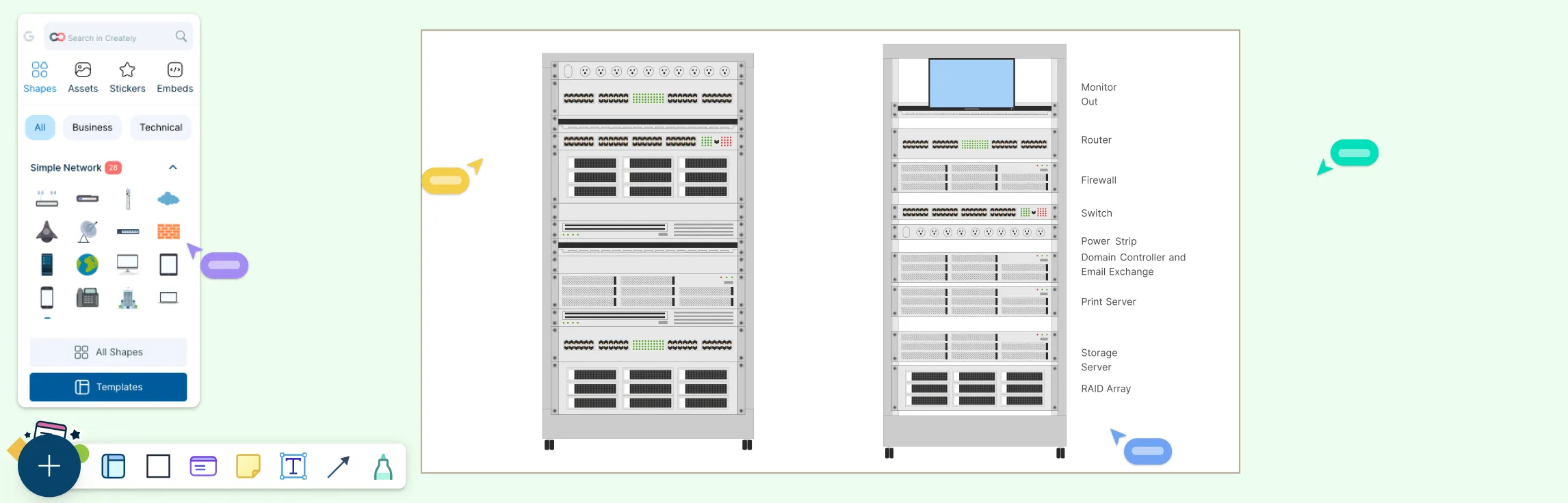
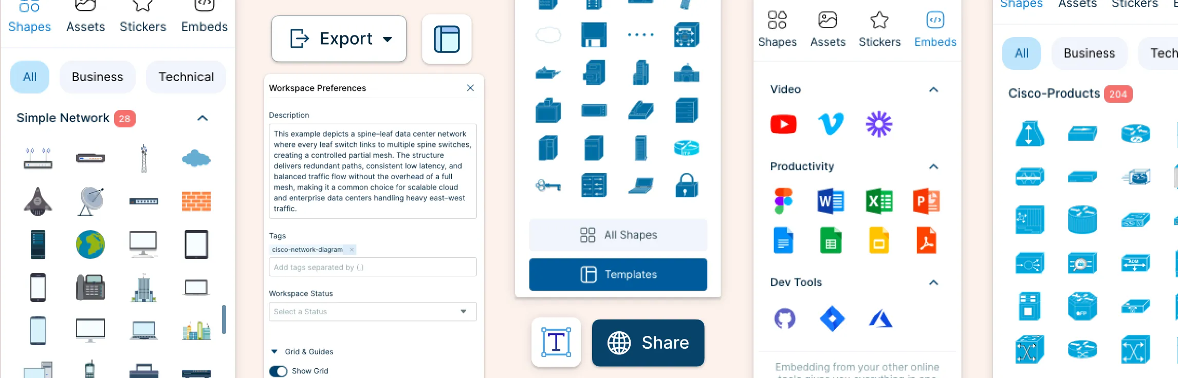
Step 2: Choose a Diagramming Tool
While there are many tools available, Creately’ Cisco diagram tool is an excellent choice for Cisco networks. It offers:
Pre-built Cisco device shapes and ready-to-use Cisco diagram templates
Easy drag-and-drop functionality
Collaboration features for teams to work together in real time
Smart connectors that adjust automatically when you move devices
This makes it simple to focus on your network design instead of spending hours drawing each icon manually.
Step 3: Layout Your Network
Start placing devices on your canvas. Use a logical flow that reflects real-world structure:
Core devices like routers and core switches go at the top or center
Distribution and access layer devices follow
Endpoints, servers, and peripheral devices are placed logically
Organize devices to minimize crossing lines and make the diagram readable at a glance.
Step 4: Label Everything
Add meaningful labels to each device and connection:
Device names (e.g., Core-Switch-01)
IP addresses or VLAN IDs where relevant
Link types and speeds (Ethernet, fiber, wireless)
Clear labeling helps anyone reading the diagram understand it quickly, whether it’s a teammate, manager, or auditor.
Step 5: Validate Your Diagram
Finally, double-check your diagram:
Ensure all devices are represented
Verify links and connections match reality
Confirm labels and IP addressing are correct
Ask a colleague to review for accuracy
A validated diagram reduces errors and becomes a reliable reference for planning, troubleshooting, and future upgrades.
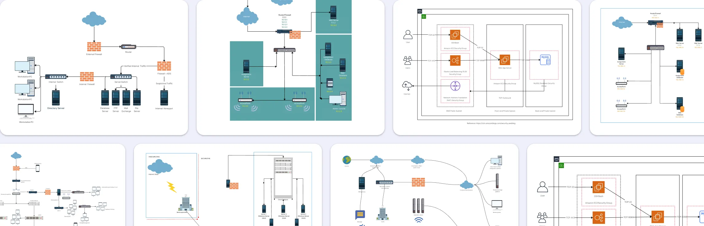
Free Cisco Network Diagram Templates
Advance Home Network With Cisco


Network with Multiple VLANs and a DHCP Server

Internet Firewall Deployment

VLAN Topology Example - Catalyst 2950-24

Access List - Cisco Network Diagram

Network Address Translation Cisco Example

Configuring a VPN

Cisco VOIP Phone Setup

Cisco Data Center Fabric - Cisco

Spanning Tree Protacol Cisco Example

FAQs About Cisco Network Topology
Who can use Cisco network topology diagrams?
What are the common mistakes to avoid when creating Cisco topology diagrams?
What’s the difference between physical and logical Cisco topology diagrams?
When should I update my topology diagrams?
How detailed should a Cisco topology diagram be?
Can Cisco topology diagrams help with troubleshooting?
How do I create a network topology similar to Cisco Packet Tracer in Creately?