Managing servers, switches, and network gear requires clarity and precision. Whether you’re planning a new deployment, reorganizing a rack, or documenting existing infrastructure, a clear visual layout keeps everyone aligned and prevents costly mistakes. In this guide, you’ll learn how to create rack diagrams that are accurate, scalable, and easy to maintain—so you can plan smarter, troubleshoot faster, and keep your infrastructure organized.
Rack Diagram Definition
A rack diagram is a visual layout that shows how equipment like servers, switches, patch panels, and power units are arranged inside a rack. It maps out exactly where each device sits by rack unit (U) height, giving you a clear front (and sometimes back) view of your setup. Instead of guessing what’s installed where, you get a structured, easy-to-read snapshot of your infrastructure—making planning, installations, upgrades, and troubleshooting much more efficient.
Rack diagrams are essential tools for those who need to visualize, plan, and maintain equipment efficiently:
- Network engineers
- System administrators
- Data center planners
- IT managers
- Infrastructure architects
What Is a Server Rack Diagram
A server rack diagram is a clear visual layout that shows how servers and related equipment—like switches, storage devices, and power units—are arranged inside a rack. It highlights the exact rack unit (U) position of each device, giving you a structured view of your setup at a glance.
With a server rack diagram, IT teams can plan installations, manage space efficiently, organize cabling, track power usage, and troubleshoot faster. It’s an essential reference for keeping server rooms and data centers organized, scalable, and easy to maintain.
Rack Diagram Components
A well-designed rack diagram relies on several key components to give a clear, organized view of your equipment and infrastructure. Understanding these elements helps you plan space, manage power and cables, and keep your data center running efficiently.
| Component | Description |
| Rack Frame and Unit Numbering | The backbone of the diagram: usually a 19‑inch cabinet with numbered units (U) that show exactly where gear fits vertically. Helps plan space and track available room. |
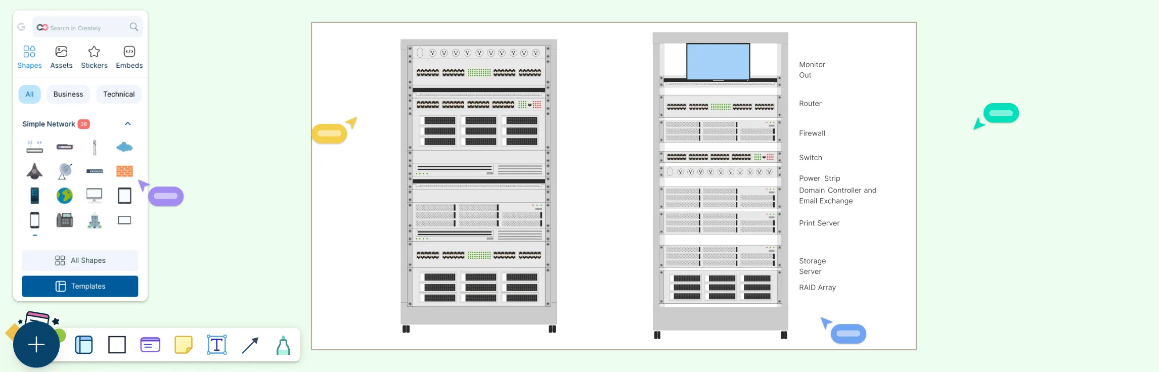
| Equipment Placement | Front-facing icons for servers, switches, routers, storage arrays, patch panels, UPS units, PDUs, and other hardware. Each item is placed at an exact U height for clarity. |
| Power Distribution Units (PDUs) | Shows where electrical power enters the rack and how it’s allocated to devices, helping prevent overloads and plan capacity. |
| Cable Routing and Management | Visual paths for network and power cables to reduce clutter, improve airflow, and simplify maintenance. |
| Labels and Metadata | Clear names, asset IDs, port numbers, and notes on equipment for fast identification without guesswork. |
| Blanking and Airflow Panels | Placeholders in empty spaces that direct cooling air efficiently and prevent hot spots. |
| Optional Views and Details | Rear views, connection lines, cooling zones, weight info, and comments on power or network paths for a complete picture of rack organization. |
Types of Rack Diagrams
Rack diagrams come in several types, each designed to serve a specific purpose in planning, documenting, and managing IT infrastructure. Choosing the right type helps you visualize equipment, streamline installation, and simplify maintenance.
| Type of Rack Diagram | Description | Best Used For |
| Front Elevation View | Shows equipment from the front of the rack with exact unit (U) positions. | Placement planning, identifying available space, ensuring equipment fits correctly. |
| Rear Elevation View | Displays the back of the rack to plan cabling, power access, and airflow. | Managing connections and maintenance without disrupting front-side operations. |
| Single Rack Diagram | Provides a detailed view of one rack at a time. | Documenting specific cabinets, planning upgrades, installation instructions. |
| Multi-Rack Diagram | Displays multiple racks side by side across a row or room. | Large deployments, coordinating equipment placement, cable runs, and airflow across a data center floor. |
| Logical Rack Diagram | Highlights functional relationships like network paths, power connections, or system hierarchies rather than exact physical placement. | High-level system planning and understanding infrastructure relationships. |
| Physical Rack Diagram | Shows precise physical placement, power allocation, weight distribution, and space usage. | Installation accuracy, capacity tracking, and audit-ready documentation. |
| Data Center Rack Layout | Combines multiple racks into a broader room or floor layout, including cooling zones and power distribution areas. | Macro-level planning and optimizing overall data center efficiency. |
How to Draw a Rack Diagram
Step 1. Define Your Goal and Gather Information
Start by identifying why you’re creating the diagram—planning a new rack, documenting an existing setup, or reorganizing equipment. Gather all relevant device details, including:
Servers, switches, storage units, UPS systems, and PDUs
Rack unit (U) height for each device
Power requirements and network connections
Any special spacing or cooling needs
Step 2. Set Up the Rack Outline
Draw a clean rack frame with all U positions numbered. Decide whether you need a front view for placement or a rear view for cabling and power planning. Make sure your diagram is to scale so every device fits accurately.
Step 3. Place Equipment Logically
Arrange devices in the rack thoughtfully:
Heavier and heat-producing equipment goes toward the bottom for stability and airflow
Group related devices together for easier cabling and maintenance
Add blanking panels in empty spaces to guide airflow and prevent hot spots
Step 4. Plan Power and Cable Management
Include PDUs, UPS systems, and power connections. Draw network and power cable paths neatly, labeling all devices, ports, and cables clearly to make the diagram easy to follow.
Step 5. Review, Optimize, and Maintain
Share the diagram with your team for feedback, check spacing, airflow, and power distribution, and update it regularly whenever equipment changes. A living diagram keeps your rack organized and your team aligned.
Examples of Rack Diagrams
Network Rack Diagram Example


Rack Elevation

Server Rack Diagram

Rack Diagram Template

Network Rack Diagram Template

Datacenter Rack Diagram

FAQs About Rack Diagrams
What is the best software to create a rack diagram?
Do I need both front and rear views?
Can rack diagrams help with cooling and airflow planning?
Are rack diagrams only for data centers?
How do I choose between a logical and physical rack diagram?
How detailed should cabling be in a rack diagram?
Can rack diagrams help with disaster recovery planning?
How do I handle multiple racks in a single diagram?