Bus topology remains one of the simplest ways to structure a network, with all devices connected along a single shared communication line. While bus topology is less common in modern enterprise networks, bus topology still appears in legacy systems, industrial environments, and specialized setups. This guide brings together practical bus topology examples to show how this layout is used across different real-world scenarios.
9 Examples of Bus Topology
1. Small Office Bus Topology Network Template
A simple bus network topology example showing multiple workstations connected along a single shared communication line, suitable for small office setups where minimal cabling and easy expansion are priorities.


2. Simple Bus Topology Example
A basic example of bus topology illustrating devices linked to a central backbone, demonstrating the core bus layout with nodes tapping into a common transmission path.

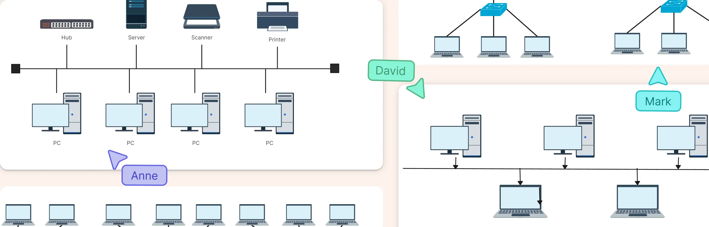
3. Star-Bus Hybrid Topology Diagram
A hybrid network combining star segments connected to a central bus backbone, showing how bus and star layouts can be integrated for balance between simplicity and scalability

4. Bus Topology Example with Switch
A network where devices connect through a shared bus but also incorporate a switch to manage traffic more efficiently, blending traditional bus structure with switched segmentation.

5. Bus Topology Network Diagram
A comprehensive view of a bus configuration with multiple nodes linked to a common backbone, useful for visualizing how data flows in a linear shared medium arrangement.

6. Linear Bus Network Topology
A straightforward example emphasizing a line-shaped backbone with devices attached sequentially, highlighting the classic linear bus layout.

7. Omni Channel Access Bus Topology Example
A conceptual bus layout illustrating how multiple channels or devices access a shared communication line simultaneously, typical in environments where broadcast or multi-node access is needed.

8. Building Automation Bus Network
An example showing devices like sensors, actuators, and controllers connected along a shared bus backbone for building systems (lighting, HVAC, security), illustrating bus usage beyond traditional LANs.

9. Extended Bus Network Topology Diagram
A larger bus configuration with more nodes and extended backbone span, showing how additional devices are integrated into a common line network for broader coverage.

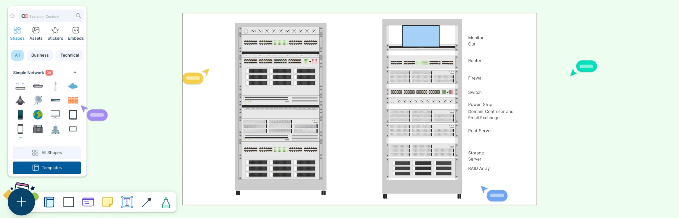
Why Use Creately to Draw Bus Topology Diagrams
When it comes to creating clear and professional bus topology diagrams, Creately’s network diagram software makes the process fast and intuitive.
Intuitive drag-and-drop interface makes placing network nodes, backbone lines, and connectors fast and easy, even for beginners.
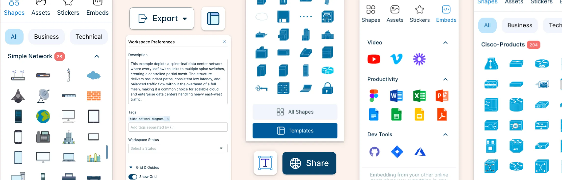
Extensive built-in shape and icon libraries tailored for network diagrams help you represent devices (computers, switches, terminators) accurately without hunting for graphics.
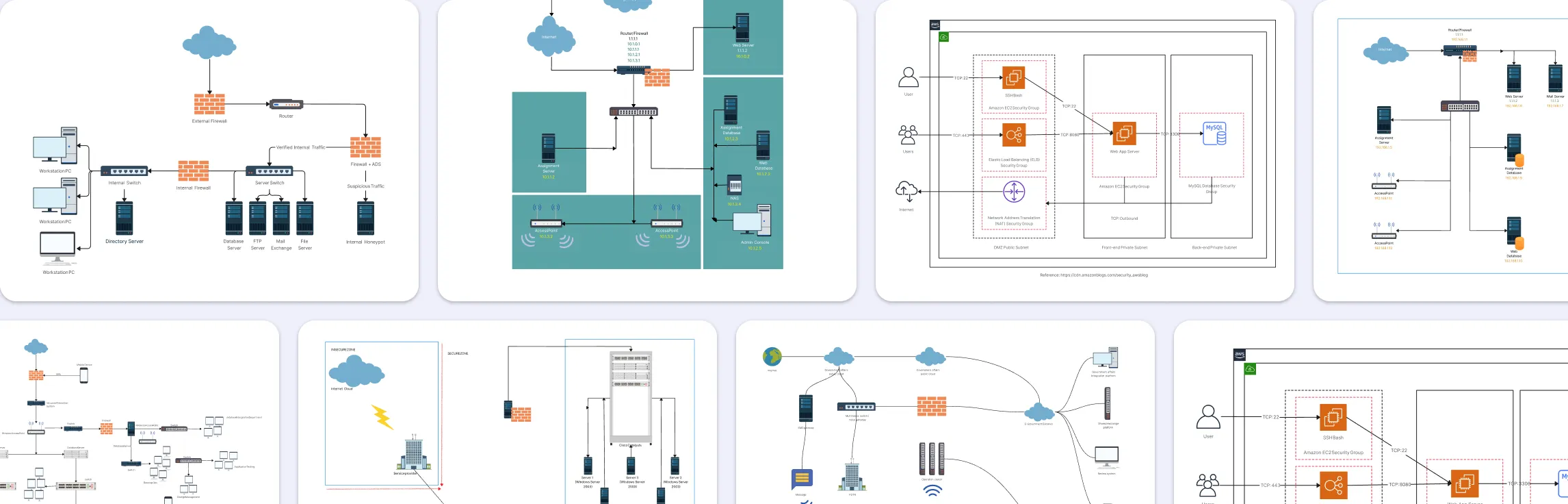
Ready-made templates (including bus and hybrid topology templates) let you start with a layout and customize from there, saving time on design.
Smart connectors automatically align and anchor lines between elements, keeping your bus topology clean and readable.
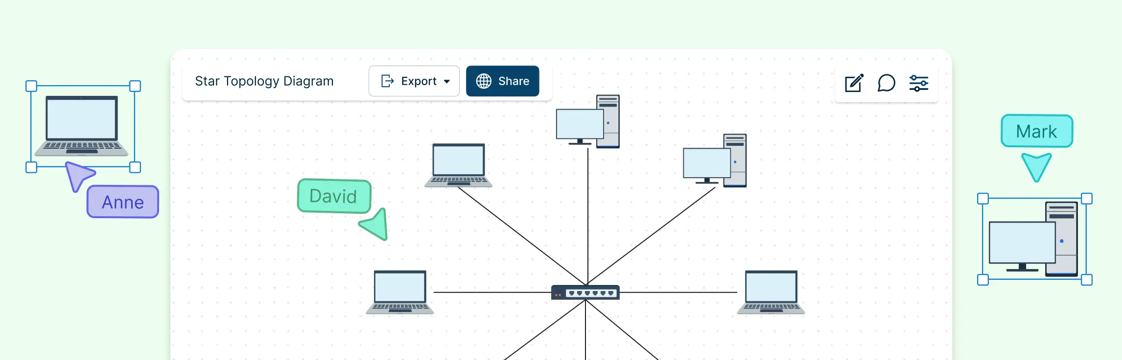
Real-time collaboration and commenting allow teams to work on and review diagrams together, leave feedback, and iterate quickly.
Version history and sharing tools make it simple to track changes, revert to previous versions, and share diagrams with stakeholders or embed in documentation.
Flexible export options (PNG, PDF, embed links) help you include topology visuals in reports, presentations, or training materials.
Data fields and annotations let you add details like device names, IPs, or notes directly on the diagram, enhancing clarity for documentation and planning.
Helpful Resources
Learn how to draw a network diagram step by step, from planning what to include to laying out components clearly and choosing the right symbols.
Discover key bus topology diagram elements, highlight common design patterns, and point out the limitations you need to account for when working with this topology.
Discover how a hybrid topology diagram effectively visualizes complex networks. Explore types, advantages & disadvantages, step-by-step creation tips, and best practices, plus free templates to plan, scale, and manage networks with ease.
Learn what mesh topology is, how it works, variations like full and partial mesh, and see clear network topology diagrams. Includes advantages, disadvantages, and free templates.
Understand how to approach Cisco network topology diagrams with confidence and create visuals that are practical, accurate, and easy to understand.
Learn how to create a home network setup diagram step by step, understand common layouts, follow practical best practices, and use free templates to map your setup.
Discover how to create a wide area network diagram step by step, understand key components, WAN examples, and follow proven best practices.
Everything you need to know about LANs, from the basics and key components to network types, advantages, and best practices.
Discover what a logical network diagram is, how it differs from a physical network diagram, why it’s useful, and how to create one.
FAQs: Bus Topology Diagram Examples
Where are bus topologies commonly used today?
Can I expand a bus topology easily?
What tools can I use to create bus topology diagrams?
What equipment is needed for a bus topology network?
How do terminators work in a bus topology?