Modern networks can look simple on the surface, but behind the scenes, traffic needs to be carefully separated, secured, and managed. This guide helps you understand VLAN diagrams by breaking them down step by step, from what a VLAN diagram is, the key components you’ll see, why it’s used, real-world examples, and how to draw one yourself.
What is a VLAN Diagram?
A VLAN diagram (also known as a virtual LAN diagram) visually shows how devices, switch ports, and network segments are organized into virtual local area networks, helping you see which devices communicate with each other and how traffic is logically isolated. Instead of focusing on cables, a VLAN diagram highlights how the network behaves, making it simpler to explain, plan, and manage segmented networks with clarity and confidence.
To learn about other kinds of network diagrams and their applications, read our network diagram guide.


Key Components of a VLAN Diagram
A VLAN diagram works best when it clearly shows how the network is logically organized. The key components below help you quickly understand which devices belong together, how traffic is separated, and where it flows.
Network devices – Switches, routers, and end devices (PCs, phones, servers) that participate in VLAN communication.
VLAN IDs and names – Labels (for example, VLAN 10 – Sales, VLAN 20 – Guest) that identify and group devices logically.
Access ports – Switch ports assigned to a single VLAN, connecting end devices to the network.
Trunk links – Connections between switches or routers that carry traffic for multiple VLANs.
Inter-VLAN routing – A router or Layer 3 switch that enables controlled communication between VLANs.
Network boundaries – Visual cues showing LANs, buildings, or logical zones to clarify scope and segmentation.
These components keep your VLAN diagram easy to read and make it clear how traffic is separated and managed across the network. Read network diagram symbols to learn how these components are represented in a network diagram.
Why Use VLAN Diagrams
Visualize network segmentation – Clearly see how devices are grouped into VLANs on the same physical network.
Improve communication – Make it easier to explain network designs to teammates, stakeholders, or non-technical users.
Plan with confidence – Spot gaps, overlaps, or misconfigured VLANs before implementation.
Simplify troubleshooting – Quickly identify incorrect port assignments, missing trunk links, or routing issues.
Enhance security awareness – See where traffic is isolated and where access should be restricted.
Document your network – Create a clear reference for onboarding, audits, or future changes.
VLAN Network Diagram Examples
The following VLAN diagram examples show how virtual LANs are commonly used in real-world networks, from separating office departments and prioritizing voice traffic, to securing guest access and managing trunk connections.
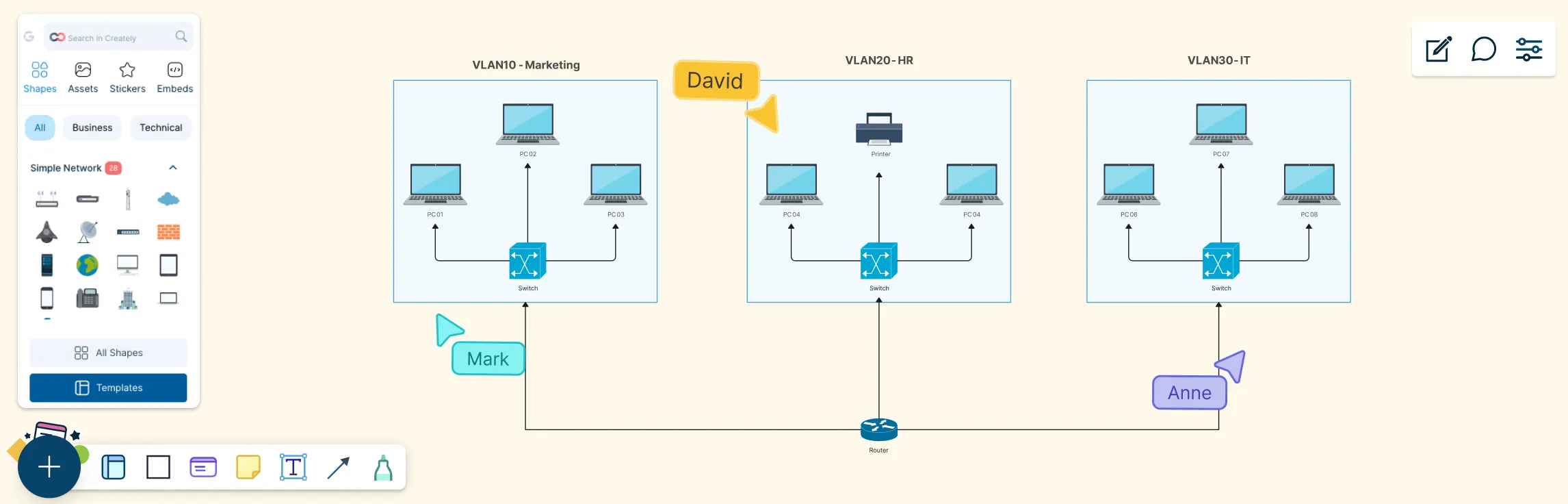
Multi-Department Office VLAN Example
In many offices, different teams share the same physical network, but they don’t need to share the same traffic. A Data VLAN groups everyday user devices like PCs and laptops by department (such as Sales, HR, or IT), keeping their traffic logically separated. In the VLAN diagram, this is shown by assigning each department to its own VLAN, which helps reduce unnecessary broadcast traffic, improves performance, and makes the network easier to manage as the organization grows.

Voice VLAN and Data VLAN Example
A Voice VLAN is designed specifically for voice traffic from IP phones, ensuring calls remain clear and reliable. In VLAN diagrams, voice VLANs often show IP phones connected to switch ports that also serve a computer, with voice and data traffic separated logically even though they share the same physical connection. This virtual LAN network setup allows voice traffic to be prioritized over data traffic, reducing delays and call quality issues.

Staff VLAN and Guest VLAN Example
This diagram shows how a single physical network can support both employees and visitors using separate VLANs. Staff devices are grouped into a Staff VLAN, giving employees access to internal systems and shared resources, while guest devices are placed in a Guest VLAN with restricted access, typically limited to the internet only. By clearly separating staff and guest traffic in the diagram, this setup highlights how VLANs improve security, reduce risk, and keep the network organized, without requiring separate hardware. This type of network VLAN is used in offices, coworking spaces, schools, hotels, and any environment that needs secure internal access alongside safe guest Wi-Fi.

Native VLAN Example
The Native VLAN is used on trunk links to carry untagged traffic between network devices. In VLAN diagrams, it is usually labeled on trunk connections to show which VLAN handles untagged frames. Clearly identifying the native VLAN helps prevent configuration errors and security issues, especially in environments with multiple switches and VLANs. This is used in networks with trunk links between switches or routers, especially in enterprise or campus environments where multiple VLANs share the same physical connections.

How to Draw a VLAN Network Diagram
Follow these steps using Creately’s network diagram software to create a clear VLAN network diagram that shows how traffic is grouped, separated, and routed across your network.
Step 1: Define the scope
Decide what you’re diagramming, such as a small office VLAN setup, a campus network, or a specific use case like staff and guest access. Keeping the scope clear helps avoid clutter and keeps the diagram easy to understand.
Step 2: Add network devices
Place switches, routers, firewalls, and end devices (PCs, IP phones, access points) on the canvas. Use consistent icons and label devices clearly so readers can quickly recognize each component.
Step 3: Create VLAN groups
Assign devices or switch ports to VLANs and label them with meaningful names and IDs (for example, VLAN 10 – Staff, VLAN 20 – Guest). Group related devices visually to show logical separation.
Step 4: Draw access ports and trunk links
Connect end devices to switches using access ports, and connect switches or routers using trunk links that carry multiple VLANs. Clearly label trunk connections to avoid confusion.
Step 5: Show inter-VLAN routing (if needed)
If devices in different VLANs need to communicate, add a router or Layer 3 switch and show how traffic flows between VLANs using arrows or labels.
Step 6: Add traffic flow and network boundaries
Use arrows to highlight important traffic paths and add boundaries such as LANs, buildings, or network zones to provide context for the diagram.
Step 7: Review and finalize the diagram
Check for clarity and readability. Remove unnecessary elements, align components neatly, and add a small legend if you’re using colors or symbols to represent different VLANs.
Advantages and Limitations of VLANs
A virtual LAN network allows logical segmentation of a physical network to improve performance, security, and manageability, but it also introduces configuration and operational complexities that must be planned carefully. Here are the advantages and disadvantages of VLANs.
| Advantages of VLANs | Limitations of VLANs |
| Better network segmentation by separating users, devices, or departments without adding physical hardware | More complex configuration requiring careful planning and correct switch and router setup |
| Improved security through isolation of sensitive traffic and reduced risk of unauthorized access | Inter-VLAN routing is required for communication between different VLANs |
| Reduced broadcast traffic by limiting broadcast domains and improving overall performance | Troubleshooting can be more difficult due to added logical complexity |
| Greater flexibility by grouping devices logically, regardless of physical location | Potential misconfiguration risks such as incorrect trunking or VLAN assignments |
| Easier network management by simplifying moves, adds, and changes without rewiring | VLANs alone provide limited isolation and do not replace firewalls or access control lists |
| Cost-effective scaling using existing network infrastructure | — |
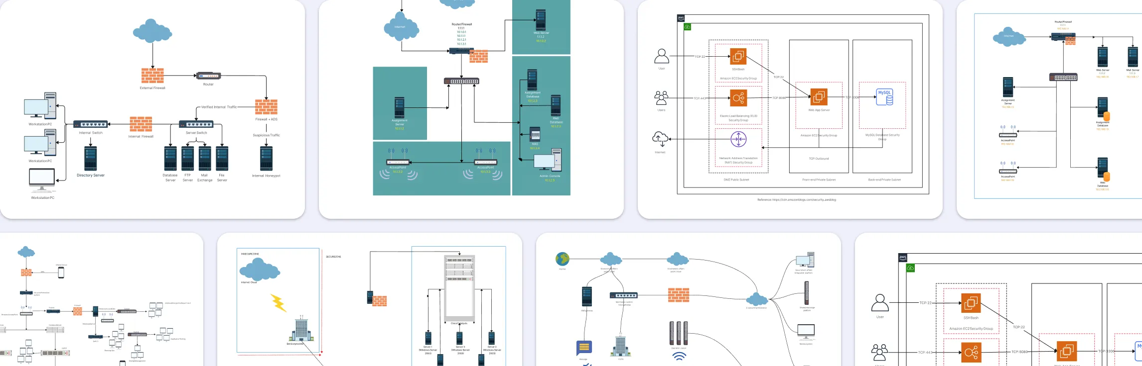
Free Network Diagram Templates to Get Started


Helpful Resources for Building Network Diagrams
Learn about the different types of network diagrams with examples.
Discover the different types of network topology and their use cases.
Learn about the Home Network Diagram and its applications.
Learn about the Wide Area Network Diagram and its applications.
FAQs about VLAN in Networking
What’s the difference between VLAN diagrams and physical network diagrams?
Do VLAN diagrams need to show IP addresses?
Do VLAN diagrams show how traffic is prioritized?
Are VLAN diagrams vendor-specific?
Resources
Aleksandr Ovcharov, et al. “Multi VLAN Visualization in Network Management.” Communications in Computer and Information Science, 1 Jan. 2022, pp. 131–143, https://doi.org/10.1007/978-3-031-23236-7_10.
Li, Xiandong, and Lijuan Yao. “Multi VLAN Reliable and Efficient Campus Network Design.” Third International Symposium on Computer Engineering and Intelligent Communications (ISCEIC 2022), 2 Feb. 2023, https://doi.org/10.1117/12.2660781.