A partial mesh network is a practical approach to building reliable networks without the overhead of fully connecting every device. This guide explores why partial mesh networks are used, where they appear in real-world architectures, and how they compare to full mesh topology designs, helping you understand and choose the right topology with confidence.
What is a Partial Mesh Network?
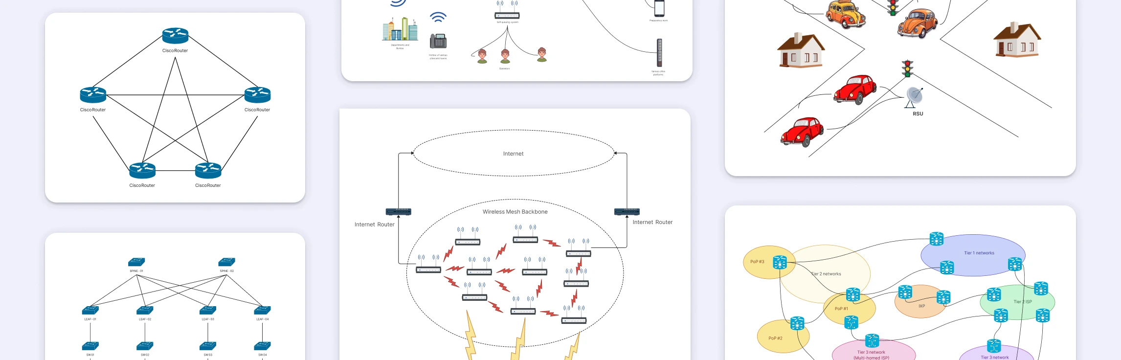
A partial mesh network is a network topology where only the most important devices are connected through multiple paths, while others use simpler connections. In network diagrams, this appears as redundant links between key nodes such as core switches or routers, with fewer connections at the edges. This clear visual structure makes it easy to see how traffic can reroute around failures, which is why partial mesh diagrams are widely used to document data centers, enterprise networks, and ISP backbones that need high reliability and scalability without the complexity of a full mesh.
To learn more about the mesh and its different types, read our mesh topology guide.
Why the Partial Mesh Network is Used
Improves reliability without full complexity – Critical nodes have multiple connections, so traffic can reroute if a link fails, while less critical nodes remain simply connected.
Reduces cost and cabling overhead – Unlike a full mesh topology, not every device needs a direct link to every other device, lowering hardware and maintenance costs.
Scales more easily – New nodes can be added without redesigning the entire network, which is ideal for growing data centers and enterprise networks.
Simplifies network diagrams and management – Partial mesh diagrams clearly highlight redundancy where it matters most, making the network easier to understand, document, and troubleshoot.
Because of these advantages, partial mesh networks are widely used in data centers (spine–leaf architecture), ISP backbones, enterprise core networks, and large-scale wireless deployments.
Real-World Examples of Partial Mesh Networks
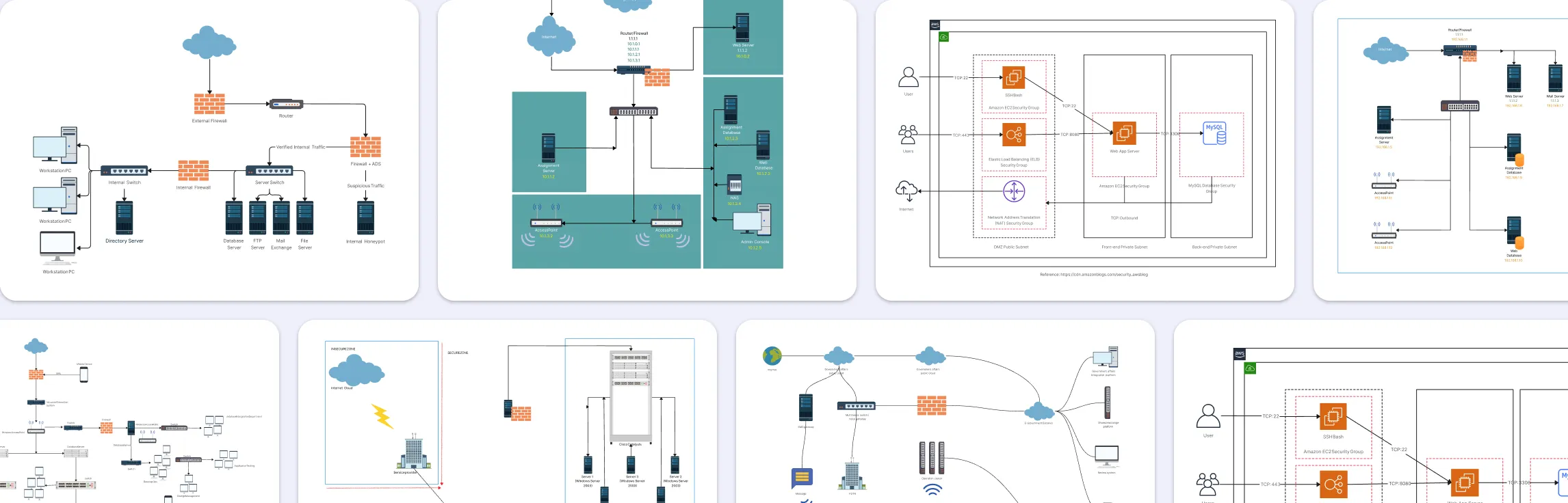
Partial mesh networks are widely used in real-world environments where reliability is essential but fully connecting every device would be inefficient or costly. Common examples include:
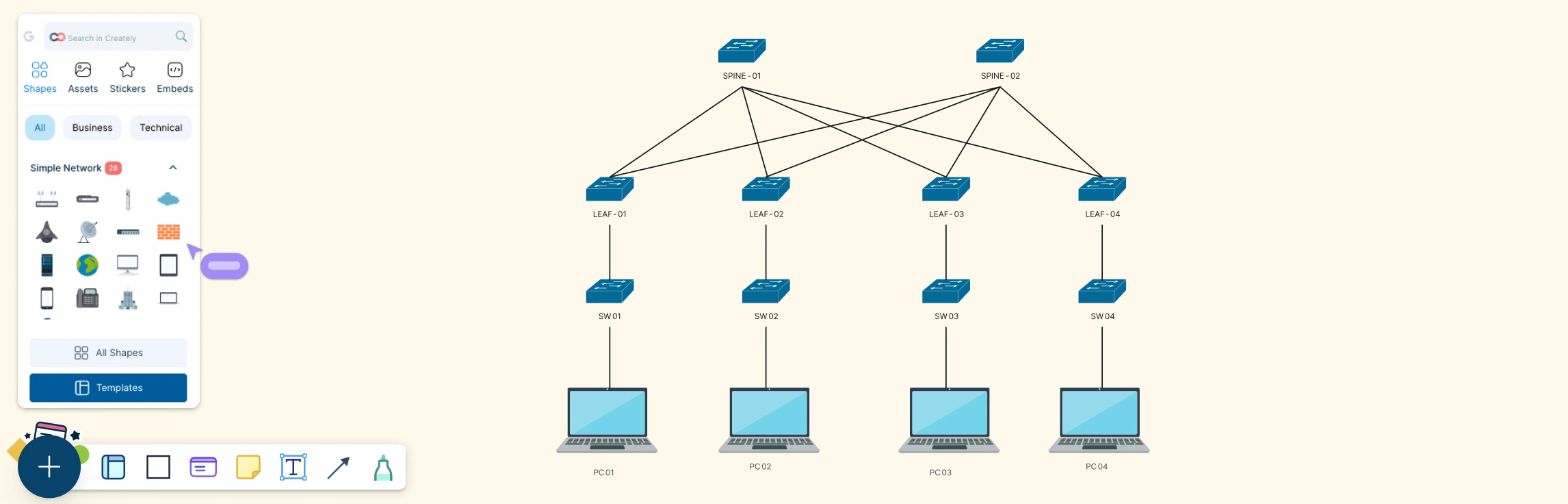
Data Center Network (Spine–Leaf Architecture)
In modern data centers, each leaf switch connects to multiple spine switches, creating several parallel paths for traffic between servers. This partial mesh design ensures low latency, predictable performance, and fault tolerance while keeping cabling and hardware costs manageable. If a spine or link fails, traffic is automatically rerouted through another spine without disrupting services.


ISP and Internet Backbone Network
Internet service providers interconnect core routers through multiple peering and transit links rather than relying on a single path. This partial mesh at the backbone level allows internet traffic to dynamically route around congestion or outages, improving global reliability and performance while avoiding the complexity of fully meshing every router.

Enterprise Core Network
In large organizations, core routers and switches are often connected with redundant links to ensure business-critical applications remain available. Access-layer devices, such as office switches or branch routers, use fewer connections. This partial mesh approach protects critical infrastructure while keeping network design and troubleshooting simpler.

Wireless Mesh for Campus and Municipal Networks
In campus or municipal wireless deployments, key access points or gateways connect to multiple neighboring nodes to provide overlapping coverage and alternate paths. End-user devices connect to a limited number of access points, forming a partial mesh that balances coverage, resilience, and network efficiency.

Government and Public-Sector Cloud Networks
Government cloud environments often interconnect multiple data centers or regions using redundant links to ensure high availability for essential services. This partial mesh topology supports secure data exchange, disaster recovery, and continuous access without the cost and complexity of a full mesh across all sites.

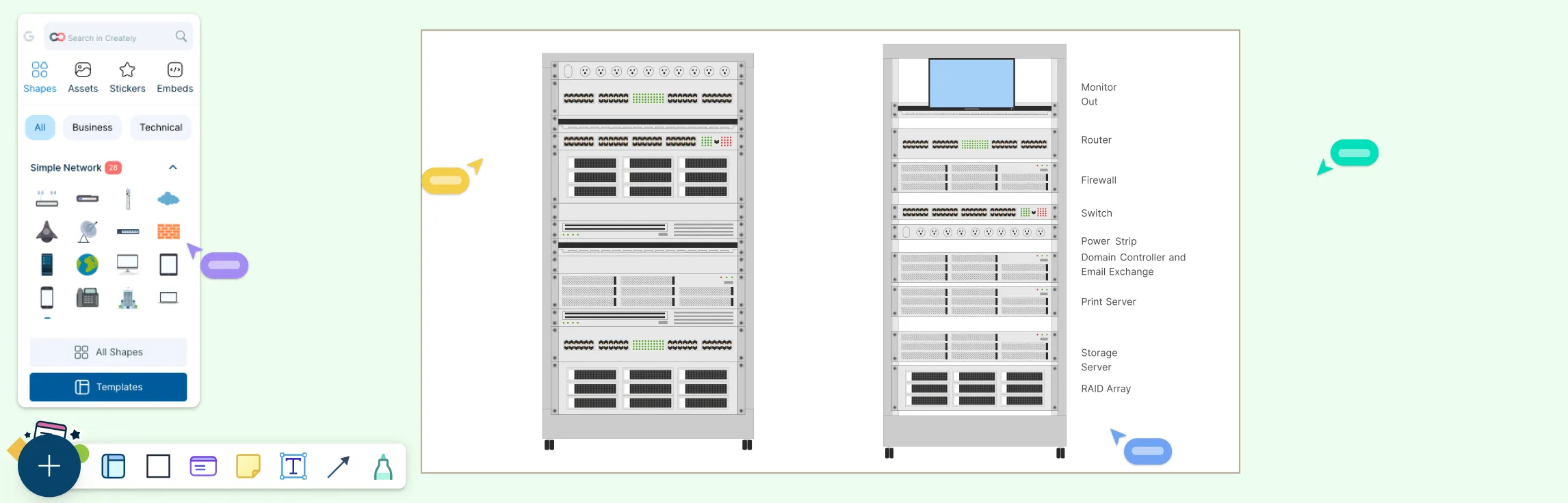
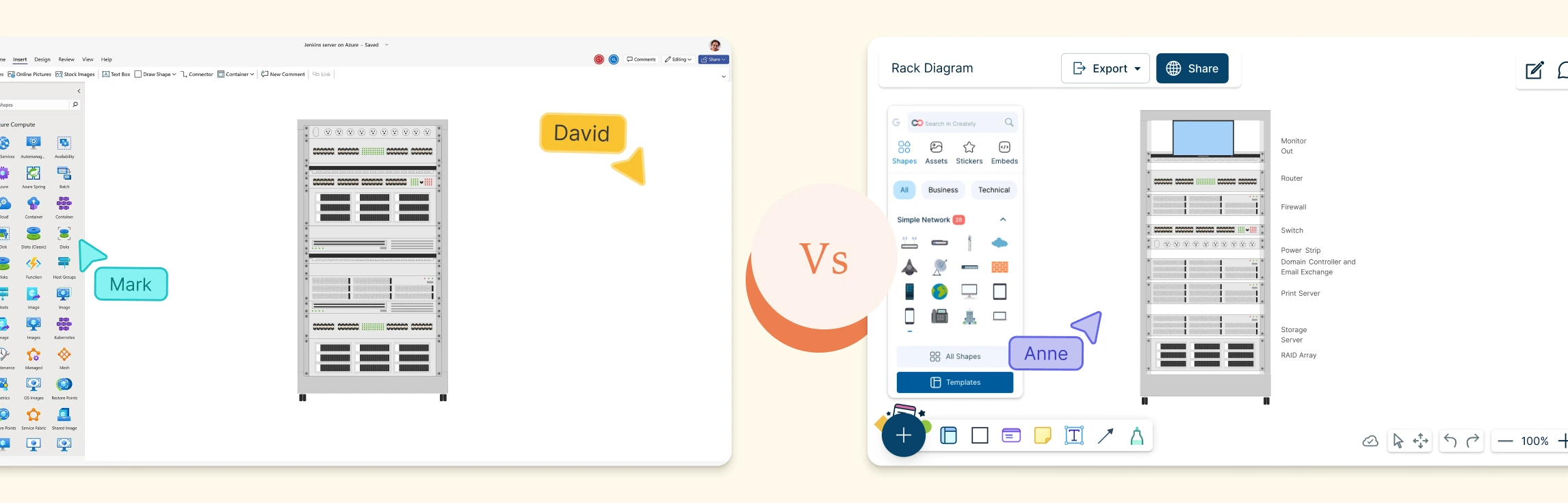
Use Creately’s network diagram software to customize these example diagrams, modify connections and components, and create your own partial mesh network diagrams tailored to your specific architecture.
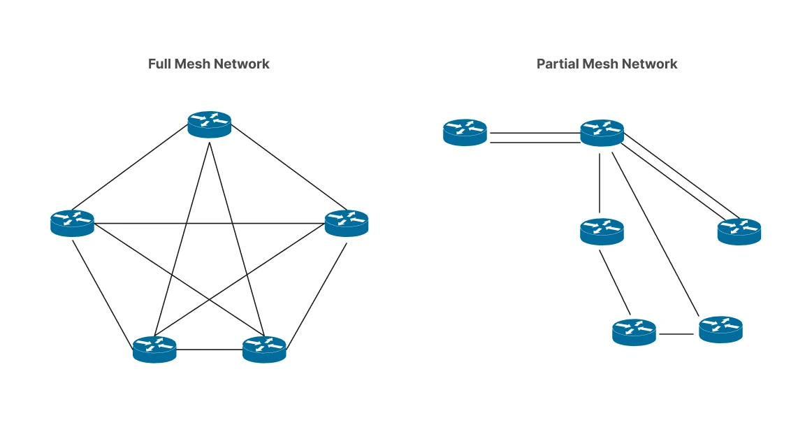
Full Mesh Vs Partial Mesh Network Comparison
The comparison below highlights how full mesh and partial mesh network diagrams differ visually and structurally, making it easier to understand why partial mesh designs are more practical for documenting real-world networks.
| Aspect | Full Mesh Network | Partial Mesh Network |
| Definition | Every node is directly connected to every other node | Only critical nodes have multiple connections; others have limited links |
| Number of Connections | Very high (grows rapidly as nodes increase) | Moderate and controlled |
| Reliability | Extremely high, as multiple alternate paths exist between all nodes | High for critical nodes, sufficient redundancy where it matters |
| Fault Tolerance | Excellent – network continues operating even with multiple failures | Very good – failures can be rerouted through key redundant links |
| Scalability | Poor – adding nodes significantly increases complexity | Good – new nodes can be added with minimal redesign |
| Cost | Very high due to cabling, ports, and maintenance | Lower and more cost-effective |
| Complexity | Difficult to design, manage, and troubleshoot | Easier to design, manage, and document |
| Typical Use Cases | Small, high-criticality systems; specialized networks | Data centers, enterprise core networks, ISP backbones, wireless meshes |
| Diagram Representation | Dense diagrams with links between all nodes | Clear diagrams highlighting redundancy at core layers |
How to Choose the Best Mesh Topology
Assess network criticality – Use a full mesh topology only if every node requires maximum redundancy; otherwise, a partial mesh is usually sufficient.
Consider network size and growth – Full mesh does not scale well, while partial mesh supports easier expansion.
Evaluate cost and complexity – Full mesh requires significantly more links and hardware; partial mesh balances reliability with cost.
Identify critical nodes – Apply mesh connections where failures would have the greatest impact, such as core routers or switches.
Think about manageability and diagrams – Partial mesh networks are easier to document, troubleshoot, and maintain.
Match the topology to real-world use cases – Data centers, enterprise networks, and ISP backbones typically benefit most from partial mesh designs.
Free Mesh Network Diagram Templates to Get Started


FAQs about the Partial Mesh Network
Full Mesh Network vs. Partial Mesh: Which is the best option?
How is redundancy shown in partial mesh network diagrams?
Are partial mesh networks fault tolerant?
Are partial mesh networks easier to diagram?
Can a partial mesh network evolve into a full mesh?
Resources
Pedro, et al. Partially Overlapped Channel Assignment on Wireless Mesh Network Backbone. 1 Dec. 2010, https://doi.org/10.1109/glocom.2010.5683886.
Yarali, Abdulrahman, et al. “Wireless Mesh Networking: A Key Solution for Emergency Amp; Rural Applications.” IEEE Xplore, 1 June 2009, https://ieeexplore.ieee.org/abstract/document/5222973