Kubernetes has rapidly become a cornerstone in modern DevOps, enabling seamless automation of deployment, scaling, and management of containerized applications. Understanding its architecture is crucial for optimizing these processes. A Kubernetes architecture diagram serves as a visual representation of the intricate components and their interactions within the Kubernetes ecosystem. These diagrams are indispensable tools for DevOps engineers, cloud architects, and IT professionals looking to design, implement, and manage Kubernetes clusters effectively.
In this guide, we delve deeper into the core components of Kubernetes cluster architecture and discuss best practices for deployment, ensuring you have a comprehensive understanding of this robust system.
What Is Kubernetes?
At its core, Kubernetes is a powerful container orchestration system. It automates the deployment, scaling, and operation of application containers across clusters of hosts, offering a self-healing, scalable platform for managing modern web applications. In a Kubernetes architecture, you commonly see a control plane and multiple worker nodes.
Visualizing Kubernetes architecture diagrams is essential because it helps teams to grasp the distributed nature of the system quickly. These diagrams provide an overview of the control plane components such as the API server, etcd, controller managers, and the scheduler. They also illustrate worker node components like kubelet, kube-proxy, and container runtime, offering insights into how they interact to manage and orchestrate containers. Moreover, diagrams can highlight how Kubernetes ensures high availability and scalability, features critical for today’s enterprise-level applications.
What Are Kubernetes Architecture Diagrams?
A Kubernetes architecture diagram is a visual representation of the various components involved in a Kubernetes cluster. These diagrams map out the infrastructure, displaying how different elements like the control plane and worker nodes interact. Essentially, they help in providing a clear picture of the Kubernetes environment, making it easier for DevOps teams and cloud architects to understand, manage, and optimize their deployments.


Core Components of Kubernetes Architecture Diagrams
Kubernetes Control Plane Components
The Kubernetes architecture is composed of several critical Kubernetes node components spread across the control plane and worker nodes. The control plane manages the overall state of the cluster, orchestrating containerized applications to ensure they run efficiently and reliably. Key components of the control plane include:
Api server: The core of the Kubernetes control plane, the kube-apiserver exposes the Kubernetes API, manages API requests, authenticates users, and authorizes actions. It acts as the communication hub, linking the control plane with worker nodes. The API server scales horizontally by deploying additional instances to handle increased workloads.
etcd: This is a distributed key-value store that serves as the brain of the Kubernetes cluster. It stores all configuration data, cluster state, metadata, and information about Kubernetes objects securely. The strong consistency ensured by the Raft consensus algorithm makes etcd essential for the proper functioning of the cluster.
Kube-Scheduler: Responsible for scheduling pods onto the appropriate worker nodes, the kube-scheduler evaluates resource requirements, availability, and affinity rules. It utilizes filtering and scoring mechanisms to determine the best placement for each pod, optimizing resource utilization and achieving efficient operation.
Kube-Controller-Manager: This component manages various controllers that ensure Kubernetes objects are maintained in their desired states. For instance, the Node Controller monitors node status, the Replication Controller manages pod replicas, and the Endpoints Controller updates endpoint objects. The kube-controller-manager is vital for maintaining the cluster’s operational integrity.
Cloud-Controller-Manager: In cloud environments, the cloud-controller-manager integrates cloud-specific APIs with the Kubernetes cluster. It manages resources such as load balancers, instances, and storage components provided by cloud service providers, enabling seamless interaction between Kubernetes and the cloud environment.
Worker Node Components
While the control plane components manage the cluster state and administration, the worker nodes are where the actual workloads run. Worker node components include:
Kubelet: The kubelet is an agent running on each worker node. It registers nodes with the API server and ensures that containers are running as expected. The kubelet reads pod definitions (PodSpecs) provided by the kube-apiserver and manages the lifecycle, health, and resource utilization of the containers.
Kube-Proxy: The kube-proxy runs on each worker node, implementing network rules to route traffic to the appropriate pods. It enables service discovery and load balancing within the cluster by managing Kubernetes Service configurations and ensuring efficient network communication. In Kubernetes setups where traffic needs to appear as originating from a specific region, such as the United States, a dedicated proxy can be configured alongside kube-proxy to handle outbound requests through US-based IP addresses.
Container Runtime: This essential component is responsible for running the containers. It pulls container images from registries, starts, and stops containers, and oversees their lifecycle. Popular container runtimes include Docker, containerd, and CRI-O. The container runtime ensures that application workloads are executed reliably.
Pods and Services: A pod is the smallest deployable unit in Kubernetes, consisting of one or more containers that share storage, network, and specifications on how to run. Pods ensure that the containers inside them share the same relative space and resource constraints. Services in Kubernetes define a logical set of pods and a policy for accessing them. They provide a stable endpoint (IP address or DNS name) to connect applications, enabling ease of discovery and load balancing.
Kubernetes Architecture Diagram Examples
IT and engineering- Kubernetes Architecture Diagram

Kubernetes Diagram Example (RBAC Model)

Kubernetes Architecture

How Kubernetes Ensures High Availability and Scalability
Replication Controllers and Replica Sets
Replication Controllers and Replica Sets are fundamental to Kubernetes’ ability to ensure high availability. They manage the number of identical pod replicas running in the cluster, guaranteeing that a specified quantity is always up and running. If a pod fails or is terminated, the controller immediately works to bring a replacement pod up, thereby maintaining the desired state of the application.
Load Balancing and Service Discovery
Load balancing and service discovery are critical for distributing network traffic evenly across backend pods, ensuring no single pod is overwhelmed. Kubernetes employs services to abstract the discovery and connectivity required to access pod groups. The kube-proxy component facilitates this by creating network rules that route traffic to the appropriate pods, which enhances the reliability and performance of applications.
Self-Healing and Horizontal Scaling
Self-healing capabilities in Kubernetes are essential for maintaining the health of the cluster. The kubelet actively monitors the health of pods. If there are any issues, such as a non-responsive pod or node failure, the system attempts to restart or reschedule the pod on a different node. With horizontal scaling, applications can manage increased demand by adding more pod instances across nodes. This can be done manually through kubectl commands or automatically with the Horizontal Pod Autoscaler, which adjusts the number of pod replicas based on observed CPU utilization or other select metrics.
Best Practices for Deploying Kubernetes
Deploying Kubernetes efficiently requires adhering to a set of best practices that ensure optimal performance, security, and resource management. Below, we delve into several crucial practices that can significantly enhance your Kubernetes deployment:
Namespaces for Better Resource Management
Namespaces are a pivotal feature in Kubernetes that allow you to partition cluster resources between multiple users. By creating separate namespaces, you can allocate resources efficiently and avoid potential conflicts. This practice not only improves resource utilization but also simplifies management tasks.
Role-Based Access Control (RBAC) Policies
Security is paramount in any container orchestration system, and Kubernetes is no exception. Implementing RBAC policies ensures that only authorized users can access or modify cluster resources. RBAC aids in minimizing security risks by assigning necessary permissions to roles and binding those roles to users or groups.
Resource Requests and Limits
To prevent resource contention and ensure pods run smoothly, it’s essential to define resource requests and limits for CPU and memory in your Kubernetes cluster. This practice helps in maintaining cluster stability by preventing any single pod from monopolizing resources, thereby promoting fair resource distribution across the system.
Resource Requests: Indicate the minimum amount of resources a pod requires to function.
Resource Limits: Define the maximum resources a pod can use, preventing over-consumption.
Employing these best practices not only enhances performance but also ensures that your Kubernetes cluster remains secure and well-managed.
Utilizing tools like Creately can be incredibly beneficial in planning and deploying these best practices visually. Creately’s interactive diagrams enable real-time collaboration, making it easier to enforce and document these practices across your team. This streamlines the deployment process, ensuring all stakeholders are aligned and informed.
Conclusion
Kubernetes architecture diagrams are vital for understanding and managing the complex structure of a Kubernetes cluster, including the control plane and worker nodes and their core components such as the kube-apiserver, etcd, kube-scheduler, and kubelet. By clearly visualizing how these elements interact, teams can deploy, monitor, and manage containerized applications more effectively. Adopting best practices like using namespaces for resource organization, implementing RBAC for security, and defining resource requests and limits for performance ensures a Kubernetes environment that is both secure and efficient.
FAQs About Kubernetes Architecture
How does Kubernetes work?
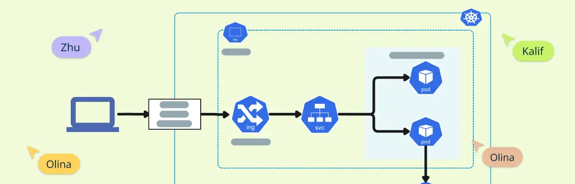
What is Kubernetes request flow in an architecture diagram?
What is a Kubernetes deployment diagram?
Is Kubernetes architecture the same as K8s architecture explained?
How does Kubernetes handle scaling?