As promised here is Part 2 of our UML post. As mentioned previously, today I will be giving you a short and sweet run through of Behavioural Diagrams, which also forms a vast part of UML diagrams. To put it simply behavioral diagrams capture the dynamic aspect of the system. The word “dynamic” in this context can be described as being the changing parts of the system.
Unlike Structural Diagrams, Behavioural Diagrams can be subdivided into five types of diagrams.
Use case Diagram:
Use case diagrams consist of a set of use cases, actors and their respective relationships. These diagrams seek to represent the use case view of a system. A diagram of this type illustrates the functionality of a system. So a use case diagram is utilized to represent the relationships that exist among the functionalities and their controllers (internal/external), which are known as actors.
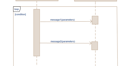
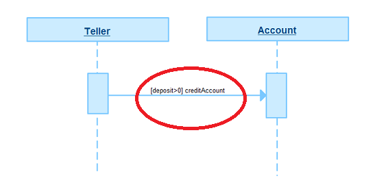
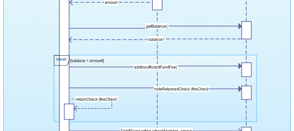
Sequence Diagram:
A sequence diagram is also commonly known as an interaction diagram. A diagram of this type deals with certain sequences, which are messages that flow from a certain object to another. It is important to note that the interaction that is present between the components of a system is significant from an implementation and execution perspective. So a sequence diagram is utilized to visualize the sequence of calls in a system when it comes to performing a functionality that is specific. Also check out this complete Sequence Diagram Tutorial to learn more about sequence diagrams.
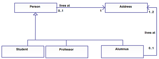
Collaboration Diagram:
Another form of an interaction diagram is known as a collaboration diagram. This type of a diagram illustrates the structural organization of the system and the messages that are sent or received. These structural organizations consists of various objects and links. The specific aim of a collaboration diagram is to visualize the organization of objects and their respective interaction.
State chart Diagram:
A state chart diagram is utilized to illustrate the event driven state change of a system. It basically describes the state change of a class and interface amongst other things. A state chart diagram is used to visually represent the reaction of a system through internal or external factors.
Activity Diagram:
An activity diagram would illustrate the flow of control in the system. This means that such a diagram consists of both activities and links. The flow is usually sequential, concurrent or even branched. The activities are the functions within a system. Ideally, activity diagrams are usually used to illustrate the flow of controls in a given system. Such diagrams are excellent when it comes to have an idea of knowing how a system will work when it is executed.
So that pretty much concludes a basic assessment of the various types of UML diagrams. I hope both posts were useful in enhancing your knowledge when it comes to software design and communication. As always, I encourage you to get in touch with us with any issues you may have with diagramming (general or specific). While I think we have substantially covered UML as a subject in this space, expect to see some interesting and thought-provoking posts starting Monday from Indu. Till then – Happy Diagramming!