Use Case Diagram Tutorial
Use case diagrams help teams visualize how people and external systems interact with a product without diving into implementation details. This guide explains what a UML use case diagram is, when to use one, which elements matter most, and how to build a diagram that clarifies scope, requirements, and stakeholder expectations.
What Is a UML Use Case Diagram
A UML (Unified Modeling Language) use case diagram is a high-level view of how actors such as users, teams, or external systems interact with a system to achieve a goal. Instead of showing screens, code, or process logic, it focuses on who needs something from the system and what outcome they expect.
When to Use a Use Case Diagram
A use case diagram is most useful when you need to explain scope quickly and align multiple stakeholders around the same functional view of a system. Teams often use one when they are:
- defining functional requirements early in a project
- comparing who can do what inside a product or service
- identifying system boundaries before detailed design begins
- preparing workshops with business stakeholders, analysts, or developers
- creating a simple reference for testing, documentation, or change requests
Why Use Case Diagrams Matter
A well-made use case diagram helps teams avoid ambiguity before they invest time in detailed specifications. It is especially helpful when you need to communicate the big picture without overwhelming people with technical detail.
- Clarify roles and responsibilities - Show which actors interact with each capability.
- Create a high-level system view - Summarize the scope of the system for managers, analysts, and delivery teams.
- Spot dependencies early - Surface external systems, support roles, and shared functionality before implementation starts.
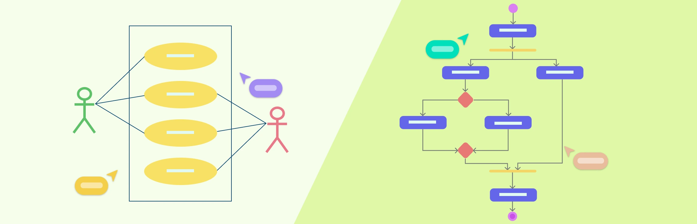
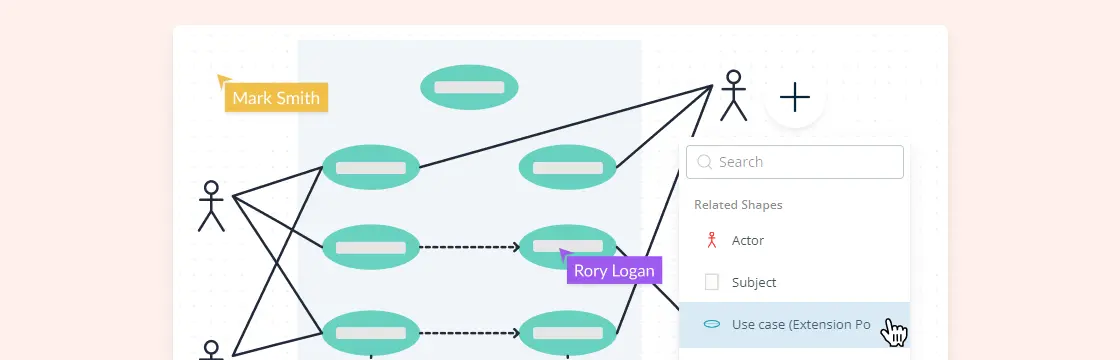
Use Case Diagram Components
Most use case diagrams rely on four core building blocks. Keeping these elements clear and consistently named makes the diagram easier to scan and reuse.
- Actor
- Use case
- System
- Package
The components are explained below.
| Symbol | Name | Description |
|---|---|---|
 | Actor | Actor in a use case diagram is any entity that performs a role in one given system. This could be a person, organization or an external system and usually drawn like skeleton shown below. |
 | Use Case | A use case represents a function or an action within the system. It’s drawn as an oval and named with the function. |
 | System | The system is used to define the scope of the use case and drawn as a rectangle. This an optional element but useful when you’re visualizing large systems. For example, you can create all the use cases and then use the system object to define the scope covered by your project. Or you can even use it to show the different areas covered in different releases. |
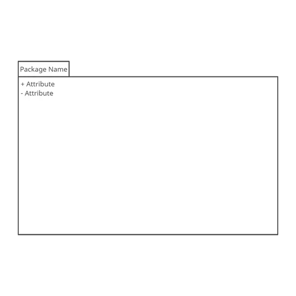 | Package | The package is another optional element that is extremely useful in complex diagrams. Similar to class diagrams, packages are used to group together use cases. They are drawn like the image shown below. |
Relationships in Use Case Diagrams
There are five types of relationships in a use case diagram. They are
Association between an actor and a use case
Generalization of an actor
Extend relationship between two use cases
Include relationship between two use cases
Generalization of a use case
We have covered all these relationships in a separate blog post that has examples with images. We will not go into detail in this post but you can check out relationships in use case diagrams.
How to Make Use Case Diagram
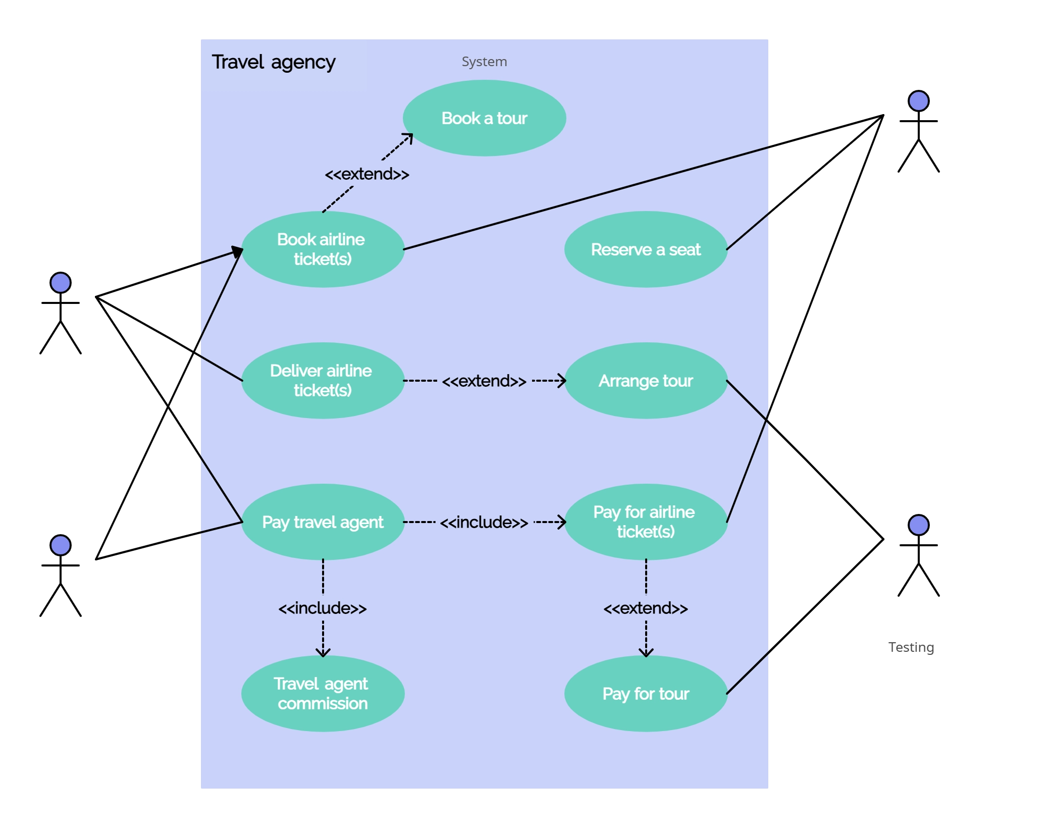
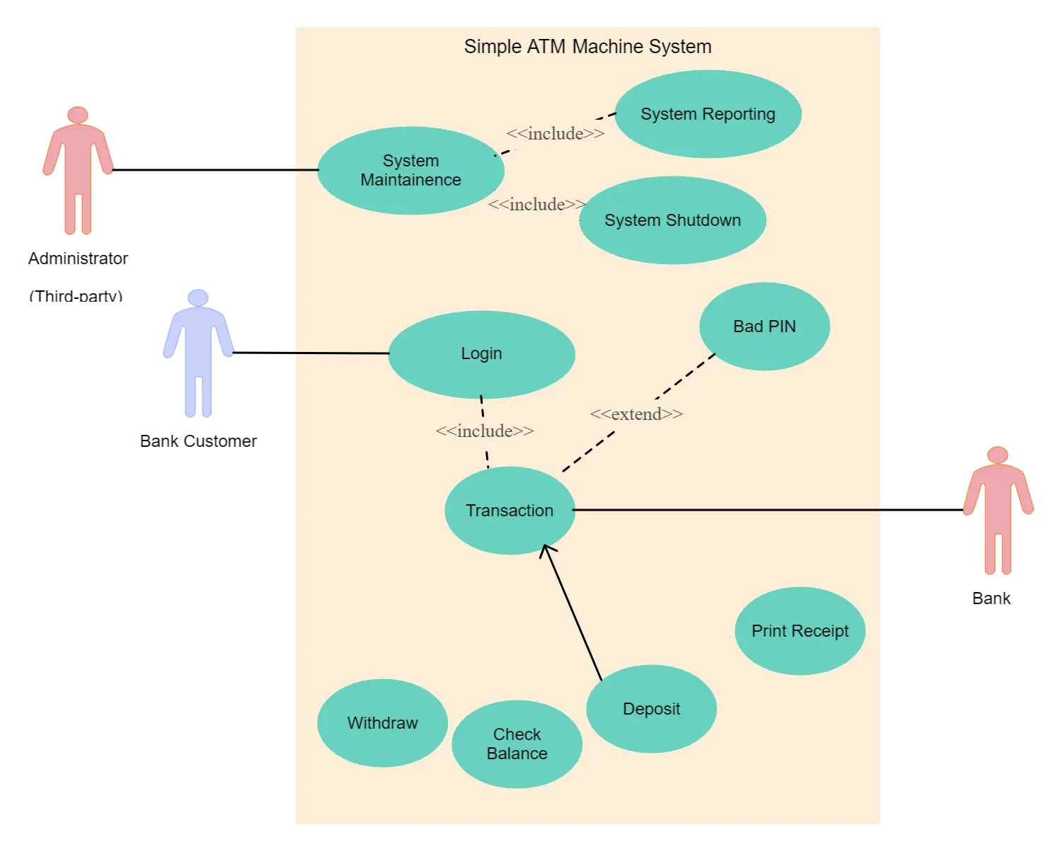
The easiest way to create a useful use case diagram is to start simple and add detail only where it improves understanding. The steps below use a banking system as an example, but the same approach works for web apps, internal tools, and service workflows.
Identifying Actors
Actors are the external people, teams, devices, or systems that interact with your system. In a banking system, the most obvious actor is the customer, but actors can also include a cashier, branch employee, payment gateway, or regulator depending on the scope you want to model.
A practical check is to ask, “Who needs something from this system or sends something into it?” If the answer is yes, that person or system is probably an actor.
Identifying Use Cases
Once the actors are clear, list the goals they need to achieve through the system. In a banking example, that might include opening an account, depositing funds, withdrawing money, requesting a checkbook, or making a payment.
Each top-level use case should describe a meaningful outcome from the actor’s point of view. Start with complete user goals first, then add include, extend, or specialized use cases only if they make the model easier to understand.
Look for Common Functionality to Use ‘Include’
Look for behavior that is reused across multiple use cases. If the same required step appears repeatedly, extract it into a separate use case and connect it with an include relationship.
Is it Possible to Generalize Actors and Use Cases
If several actors or use cases share the same behavior with a few role-specific differences, generalization can make the diagram clearer. A payment system, for example, might generalize “Make Payment” into more specific variations such as card, cash, or check payments.
Optional Functions or Additional Functions
Some behaviors happen only when a condition is met. In those cases, the extend relationship helps you show that the additional behavior depends on the base use case but is not always triggered.
Extend does not simply mean “extra.” The base use case should still make sense on its own even if the extending use case never runs.
Common Use Case Diagram Mistakes
Before you finalize the diagram, check for a few common issues that reduce clarity:
- adding too much implementation detail, such as UI steps or backend logic
- drawing every exception and edge case into the first draft
- using vague names like “process request” instead of clear actor goals
- mixing business actors and internal modules without defining the system boundary
- making the diagram so dense that stakeholders cannot read it quickly
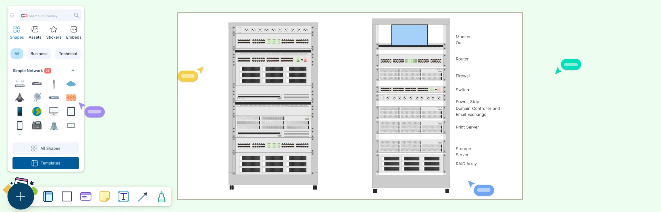
Use Case Diagram Templates


Browse our full library of customizable use case templates.