Here is an overview of all the nine different kinds of Modeling diagram objects that are wrapped under the heading of the UML.
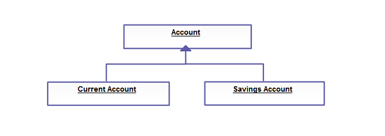
- UML Class Diagrams
- UML Use Case Diagrams
- UML Object Diagrams
- UML Sequence Diagrams
- UML Collaboration Diagrams
- UML Statechart Diagrams
- UML Activity Diagrams
- UML Component Diagrams
- UML Deployment Diagrams
All these UML diagram objects are available in Creately and you can try out a demo or take a look at some sample UML Diagrams for more context.
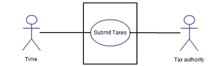
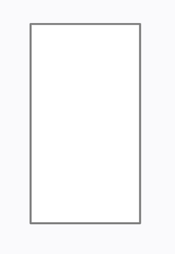
System

A system in a UML Use Case Diagram is a rectangle spanning all the use cases in the system that defines the scope of your system. Anything within the box represents functionality that is in scope and anything outside is not. Note that the actors in the system are outside the system.
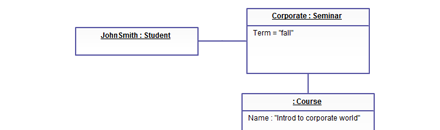
Simple Object
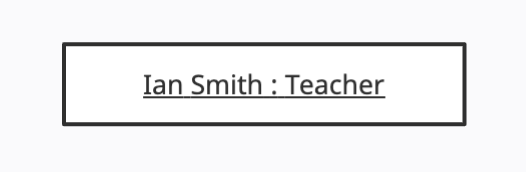
The simple object from the UML Object Diagram is a rectangle that displays the object name. This object’s name is usually underlined.
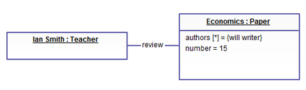
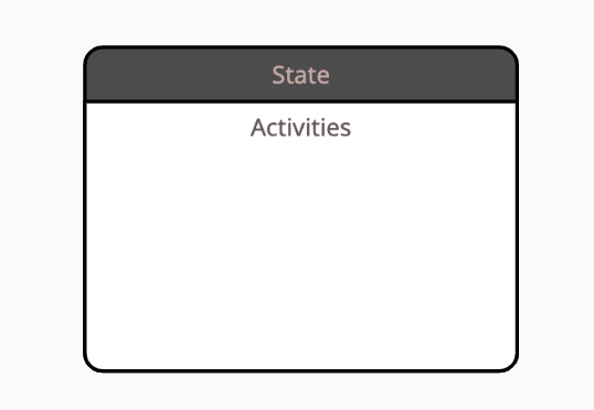
Object
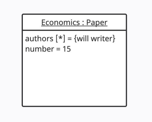
The object element from the UML Object Diagram is a rectangle divided into two parts. The top part contains the name of the object, while the second part contains the attributes of the object. Note: This element should not be mistaken with the Class element which is divided into three parts.
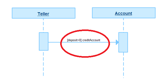
Activation
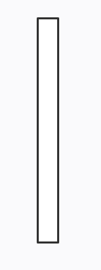
Activation elements in the UML Sequence Diagram are boxes on the lifelines. These are also called the method-invocation boxes, and indicate that an object is responding to a message. It starts when the message is received and ends when the object is done handling the message.
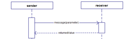
Message Arrow
Message Arrow in the UML Collaboration Diagram shows the interaction between the commencing object and the destination object.
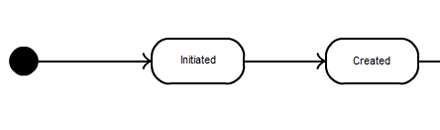
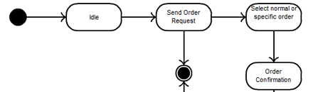
Initial State

The Initial State from the UML Statechart Diagram is the state of an object before any transitions. For objects, this could be the state when instantiated. The Initial State from the UML Activity Diagram marks the entry point and the initial Activity State. The notation for the Initial State is a small solid-filled circle. There can only be one Initial State on a diagram.
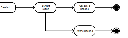
End State

End state from the UML Statechart Diagram marks the destruction of the object whose state we are modeling. The Activity End in a UML Activity Diagram shows the termination of the activity. The End notation is shown as a circle surrounding a small solid-filled circle.
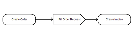
Activity
Activity state in a UML Statechart Diagram and UML Activity Diagram marks an action by an object. The notation for this is a rounded rectangle.
Junction
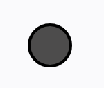
Junction state in a UML Statechart Diagram are vertices that are used to chain together multiple transitions. They are used to construct compound transition paths between states. A junction is represented by a small black circle.
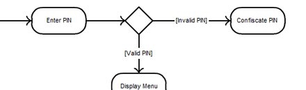
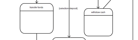
Choice

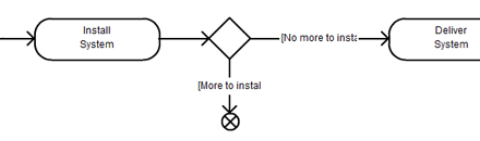
Choice state in a UML Statechart Diagram evaluates the guards of the triggers of its outgoing transitions to select only one outgoing transition. The decision on which path to take maybe a function of the results of prior actions performed in the same run-to-completion step. A choice pseudostate is shown as a diamond-shaped symbol.
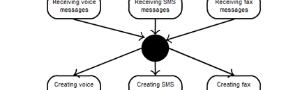
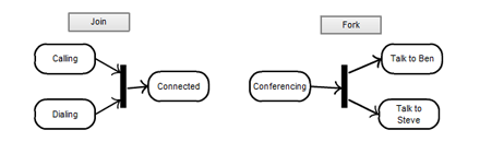
Fork / Join
A Fork notation in a UML Activity Diagram is a control node that splits a flow into multiple concurrent flows. This will have one incoming edge and multiple outgoing edges. A join node is a control node that synchronizes multiple flows. This will have multiple incoming edges and one outgoing edge.
Fork vertices in the UML Statechart Diagram serve to split an incoming transition into two or more transitions terminating on orthogonal target vertices. The segments outgoing from a fork vertex must not have guards or triggers. Join vertices serve to merge several transitions emanating from source vertices in different orthogonal regions. The transitions entering a join vertex cannot have guards or triggers.
You can easily create them online using our activity diagram tool.
Composite State
A composite state in a UML Statechart Diagram is a state that has substates (nested states).
Object
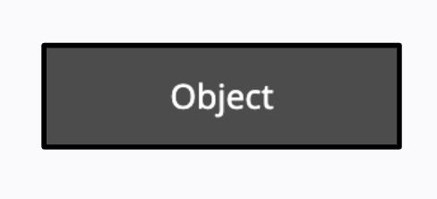
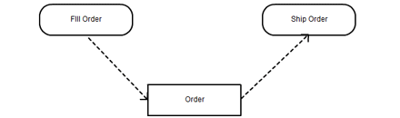
The Object notation in a UML Activity Diagram is an activity node that is used to define the object flow in an activity.
Flow End

The Flow End node in UML Activity Diagrams is a control final node that terminates a flow. It destroys all tokens that arrive at it but has no effect on other flows in the activity. This is a small circle with an X inside.
Signal Receipt

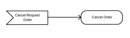
Signal Receipt notation also called the Accept event action in a UML Activity Diagram is an action that waits for a specific event to occur. This is drawn as a concave pentagon.
Signal Sending
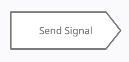
Signal Sending in UML Activity Diagram is an action that creates a signal instance from its inputs and transmits it to the target object, where it may cause the firing of a state machine transition or the execution of an activity.
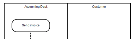
Activity Partition
Activity Partition in a UML Activity Diagram is either horizontal/vertical swimlane. The partitions are used to separate actions within an activity diagram.
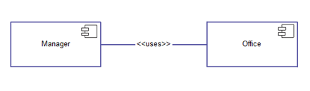
Component
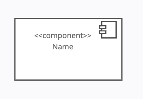
A Component UML Component Diagram represents a modular part of a system. A Component element in a UML Deployment Diagram represents a distributable piece of implementation of a system.
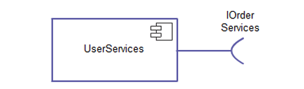
Provided Interface
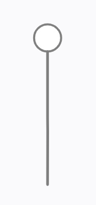
A Provided Interface of a component in a UML Component Diagram describes the services that the component offers to its environment. This is modeled using the lollipop notation.
Required Interface
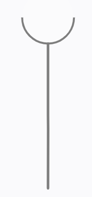
A Required Interface of a component in a UML Component Diagram declares the services that the component expects from its environment. This is modeled using the socket notation.
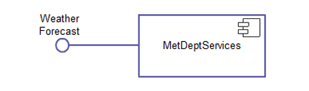
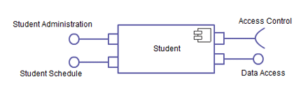
Provided Interface & Required Interface with Port
A Provided Interface with Port in a UML Component Diagram specifies a distinct interaction point between the component and its environment. Ports are depicted as small squares on the sides of components.
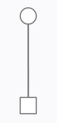
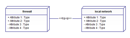
Node
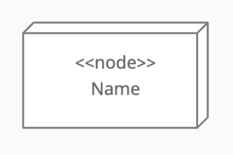
A Node element in a UML Deployment Diagram is anything that performs work in the system. This can be either hardware like personal computers; or software like the operating system, database server, and so forth.
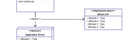
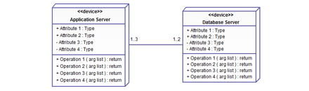
Device
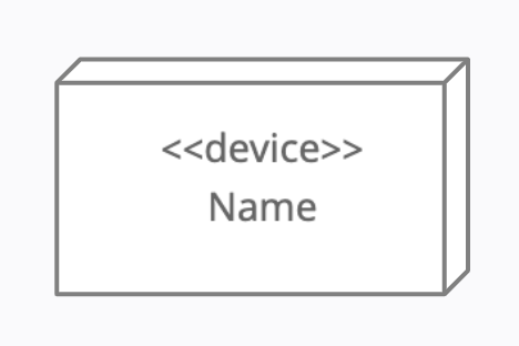
A Device element in a UML Deployment Diagram is a type of node that represents a physical computational resource in a system, such as an application server.
Deployment Specification
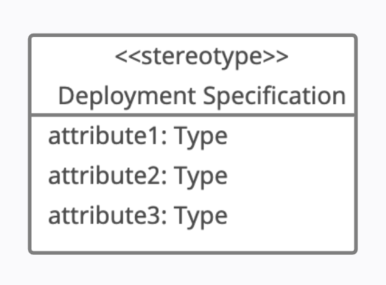
A Deployment Specification element in a UML Deployment Diagram is a configuration file, such as an XML document or a text file that defines how an artifact is deployed on a node.